PC900/4ha5 or 6gk5 for vari mu compressors

GroupDIY Audio Forum

Help Support GroupDIY Audio Forum:

This site may earn a commission from merchant affiliate links, including eBay, Amazon, and others.

rafafredd

Well-known member
Joined
Jun 3, 2004
Messages
2,409
Location
Rio, Brazil
So, I just happen to have tons of those things, and I was looking at the datasheets and trying to come up with a first stage for a mic preamp, but I don´t think it´s that good for this.

On the other hand, the cutoff-point of those things looks quite "remote". Do you think those would be usefull as VariMu stage in a compressor?

Here are some links:

http://www.mif.pg.gda.pl/homepages/frank/sheets/010/p/PC900.pdf

A 6volt version:

http://www.mif.pg.gda.pl/homepages/frank/sheets/135/6/6HA5.pdf

and the 6gk5:

http://www.mif.pg.gda.pl/homepages/frank/sheets/106/6/6GK5.pdf
http://www.mif.pg.gda.pl/homepages/frank/sheets/127/6/6GK5.pdf
http://www.mif.pg.gda.pl/homepages/frank/sheets/135/6/6GK5.pdf

What do you think? I have so many that I could even parallell them like in a fairchild comp, if this would lead me to better results...
 
> Do you think those would be useful as VariMu stage in a compressor?

Could work great. Looks like you could drop them into my "12AU7" limiter and they would work, though the idle plate current will be awful high so you need to beef-up the B+.

Not sure it would work a lot better. Little lower noise but little lower overload point. Might be a hair less dynamic range than dumb old 12AU7.

> I have so many that I could even parallel them like in a fairchild comp, if this would lead me to better results...

There is a threshold that is hard to reach. The Fairchild manages enough output from the vari-Gm stage, even when gain is reduced, that it does not need a post-amp to drive a load. If you can't make that much output, which is very hard to do, then you need a post-amp anyway and paralleling has no real advantage (except in winter). I'd have to sleep and think before I could guess if enough of these could give enough output in deep GR to lose the post-amp, before your studio burned down. I do think you would have to have a Fairchild-like output transformer: very high impedance with very high DC tolerance, Big Bucks.
 
At Gm of 20,000uMho, you could use a long-tail pair as a transformerless hollow-state mike input. Noise resistance is around 300Ω, a little higher than a dynamic mike but often usable. A sufficiently clever circuit could accept Phantom power at the input without grid coupling caps, though because noise current is near zero you could use good/small film caps instead of the many-uFd electros we need for BJT inputs. Gain could be quite good, over 30 in the input pair, so you could be a little sloppy in the second stage.

You could also build a small power amp. You can probably pull a half watt per tube, stack em up to the desired power. To get maximum power you may have to work AT the ratings, which in this case (TV Tuner tube) is not a long-life condition, maybe 100 hours instead of 10,000 hours for many small tubes worked a bit below the ratings. But if you got lots....
 
Thanks PRR. Yes, maybe trying to drive a transformer with the varimu datage is a bit silly, unless I wanna come wth a new 10k dollars compressor design, like the Fairchild. And that´s definetly what I don´t want. Maybe, as I have lots, I could use two as the vari gan stage and two as the transformer driving stage. It would probably drive 10kCT to 600 transformer nicely, no?

For the varigain stage, do you think I can get along with your 12au7 stage with a B+ of 200v regulated?

About the transformerless mike amp, you really got me interested. I didn´t thought that this cheap tube could give me a 300ohms input noise resistance. But I also don´t think I´m smart enought to draw a schematics for this. I don´t care to use small film caps for grid coupling when phantom is aplyed, really.... Maybe I´ll try drawing something and post here...

Thanks for all!
 
> I didn´t thought that this cheap tube could give me a 300ohms input noise resistance.

A TV in the TV-store show room has to pick up every channel that other TVs do: it has to have high gain and low noise or buyers will think it isn't very good. But it also has to be just as cheap as every other TV. So a lot of effort was spent on high gain low noise antenna input tubes.

Most of this was wasted effort. When you get the TV home, you mostly watch strong signals. As soon as a signal is strong enough to give a good picture, the AGC system of the TV reduces the gain to keep from overloading. For most people and most signals, the input tube really lived at 1/10th to 1/100th of maximum gain and current. And heat. My suspicion is that some of these little gain-bottles can't really be kept at their ratings for thousands of hours, like a 12AT7 (which is originally a low-performance VHF tuner tube) can. Don't run 6HA5 at 2.6 Watts and expect long life.

> I can get along with your 12au7 stage with a B+ of 200v regulated?

You need more current than my low-cost supply design will give. IIRC my 12AU7 ran about 6mA both sides, the 6AH5 and similar hot tubes want to go 20mA each, 40mA for both. If they also run 200V they will die fast.

As I read the curves, up to 12dB-15dB limiting there is no real advantage, and a lot more heat. With some major circuit redesign, we might be able to push 6AH5 to 30dB-40dB gain reduction without gross distortion, but it it still music?

I think B+ about 100V-125V, 1K plate resistors, a little negative grid bias to set the idle current to 5mA-10mA per tube. This negative bias has to be Fixed, not cathode-resistor, so it complicates the sidechain. Alternatively, zero-bias and reduce B+ toward 60V to set idle current around 10mA per tube. At such low plate voltage you will probably have to reduce sidechain gain to keep a respectable output level.

> It would probably drive 10kCT to 600 transformer nicely, no?

It may do OK at 10KCT load. B+ can't be much over 200V, idle current could be 5mA/tube fixed bias (about -3V) or 7mA-10mA per tube cathode resistor bias (try 100 ohm common cathode resistor). Peak drive about 2V or 3V per grid, power about 1 Watt at clipping. Overall efficiency is terrible: high plate loss, large heater demand. But if the tubes are really cheap, why not?

> transformerless mike amp

http://www.tubecad.com/october99/page16.html

There are problems with Broskie's understanding of studio mike interfacing, but it is a start. Six halves of selected 6DJ8 gives very low noise; for LD condensers you could do fine with two tuner triodes for the input.
 
With some major circuit redesign, we might be able to push 6AH5 to 30dB-40dB gain reduction without gross distortion, but it it still music?

mmm... I use 25-35dB compression on my STA-level all the time. Am I just freak for doing it? :?
 
Matching tubes in the push pull audio stage, and matching them across the whole control voltage range is essential to low distortion in deep GR.

With a quartet of 6BA6 triodes, my THD at -20 dbgr is .6%.. still music.
With only 4 tube sections, I can make up 20 db without a post amp.
 
PRR,

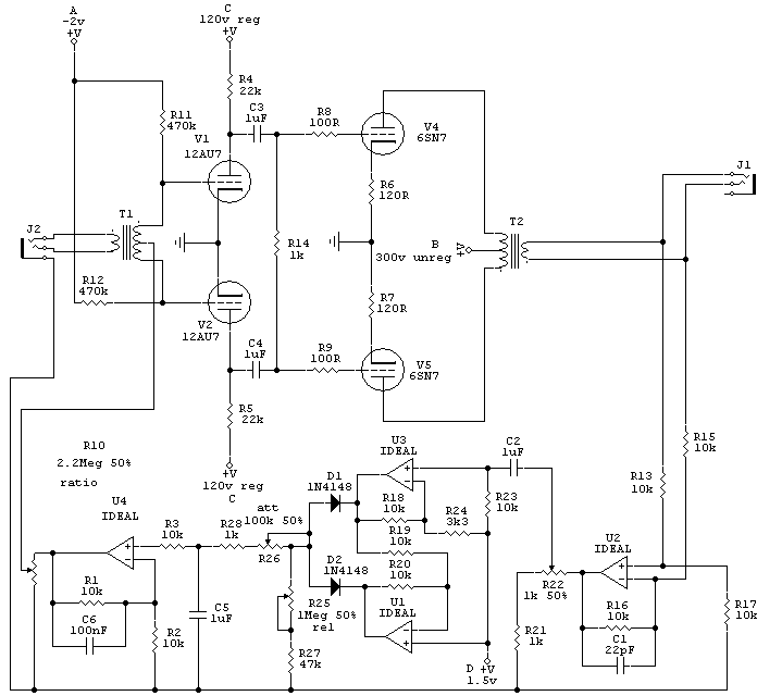
I´ve drawn what I THINK I need. This is in fact a variant on your 12au7 compressor. If the schematics somehow looks funny, sorry, I´m still very dumb when it comes to electronics design. In my dumb mind that´s what I think would be a good circuit for my purposes. It´s pretty much a modified PRR varilimiter.

About substituting the 12au7 for the PC900, would you change any components? I have many PC900 and many 6CG7, and that´s what I was actually thiking of using.

The transformers are 2k4:10k for the input and a 10k:600 for the output. I do have a source for this transformers at $20.00 a piece, so, that would make a very cheap compressor.

Maybe I´ll make a PCB only for the sidechain, and make the tube part PtoP. That would be a little board with one TL074 for single and two for stereo...

So, if it´s all wrong, I´m sorry to mess with your well done master work :?, and yes, I´m shamed even to try :oops: , but please, if this is the case come to my rescue. :thumb:

PC900_comp.gif
 
Looks mostly workable.

R14 won't work with 1uFd caps. Since you omitted the interstage iron, just leave it out, and reduce the V1 V2 plate resistors to maybe 5K or 10K.

Since you omitted the interstage transformer, any thump will clip V3 V4. It will be less of a problem if V3 V4 have a common cathode resistor, maybe large like 2K, with the grid resistors returned to a small positive voltage to get V3 V4 flowing good current. Also make C3 C4 barely big enough to meet your bass specification, so the thump is not prolonged. (For tracking non-bass instruments, you might want to switch this up to ~150Hz.)

6SN7 sure does not need grid-stoppers for stability, if your layout doesn't suck. You should try with small/no grid-stop, and also with like 10K grid-stop: this will give two different effects when thump tries to drive the V3 V4 grids positive.

Turn the input transformer around. The maximum input to this hot tube is less than a volt, you do not need step-up. Or that is my guess: obviously you can try both ways at no cost.

That connection of diff-amp to output winding "spoils" a great feature of an output transformer: total isolation. For studio use, should be zero problem: everything in the studio is on similar ground.

The 2.2Meg pot can be, and should be, much lower. You have to drive all the stray capacity of the transformer. Say 10K. Or implement the Ratio control by changing the gain of U4. Or omit U4 and make both R24 and the 1.5V reference variable. You may have to do this to scale the control voltage for this tube and for your desired output level.

And: as long as you deviated this far, why not scrap the sand-state entirely, and use the classic Tube Limiter topology such as seen in thread "Another vari-mu: Chi*wik Reach Compressor"? As we see in that thread, they made 10 or 100 of them and kept refining the design, but they managed to sell #14 and maybe even #1. A really high-class industrial limiter wants another tube between gain-cell and output, but a high-strung musical limiter is apparently possible with just two twin-triodes and NO sand (maybe for signal rectifier, where it makes little difference).
 
Regarding thump, Rafafredd, I made an interesting discovery when measuring my Fairchild clone. It has a cathode balance pot for the mu tubes.

I was testing the limiter with a gated sine wave 1sec on, 1 sec off and scope-ing the DC control voltage to look at attack and decay shapes across the time constants.

I discovered that the waveform would overshoot or undershoot when dropping to its further negative gr point. Upon setting the cathode balance pot for a square waveform, the limiters thump went away greatly.

I guess the symmetry of how the push pull mu tubes were being grid loaded was reflecting back into the control waveform.

The point at which the cathode pot ended up was consistent with minimum hum and thd so it was balanced in those areas too.

Maybe a balance pot in there... If you put one in, try that test, I'm curious what you see=)

Larry
 
Good info. Thanks for this.

The problem with this circuit is that it doesn´t use cathode resistors in the vari stage... Should I try a grid bias balancing pot?
 
Dr Mu (PRR).. would 500 ohms per leg be ok for the cathodes here?
Maybe a 1k lin pot. a 500 ohm or 250 ohm would be better but harder to find.

Oh and that would require a 2-4uf np cap from cathode to cathode too, i forgot.
 
nice info.

So, I should try a balancing pot in the grid bias, no? As you see, I don´t have a cathode resistor in the vari stage.
 
> I was hoping PRR would jump in here and say that some cathode resistance was ok.

You have the working limiter, you try it.

My sims and theory (assuming perfect match tubes) say that any cathode resistance degrades the maximum limiting you can get.

But with unmatched tubes (real tubes are never as perfectly matched as sim tubes), you certainly need a trim.

A reasonable compromise seems to be less than half the intrinsic cathode resistance, or no more than 0.5/Gm, where Gm is the transconductance at idle. This will give some trim at maximum gain yet be almost negligible in deep reduction.

For PC900 working at 125Vp -1Vg 10mA, Gm=14mA/V so 1/Gm is 70 ohms and 35 ohms might be a max. This gives a 0.35V drop, which is significant compared to the 1V bias.

You could use a 50 ohm pot: if the tubes happen to match, each gets 25 ohms. If you have to crank the pot to the end, 50 ohms in one side and 0 ohms on the other, you should probably try another tube. If you can null the unbalance anywhere in the middle, it's good. Note that if the trimmer wiper loses contact, all signal stops, so it better be good. 50 ohm trimmers are rare; maybe 100 ohm trimmer plus two 47 ohm fixed resistors, one across each side of the trimmer. This also passes signal when the wiper fails, so you lose balance but capture the moment with a little thump.

You should first be sure your plate circuit is in balance. If you have two large resistors, as in many low-price limiters, they should be better than 5% match, preferably 1%. If you use a center-tap transformer ala Fairchild, the low frequency balance (where thump happens) is assured if the winder counted turns correctly, but the HF balance of a hi-Z winding is always tricky.
 
There ya go, Rafafredd, the designer says a small amount of R is still tolerable and may help balancing. Let me know if the overshoot and undershoot during attack on the dc control waveform happens on this design.=) It became a convienient test signal for me to balance the tubes in my Fairchild circuit.
 

Latest posts

Back
Top