Modding a Chameleon 7602?

GroupDIY Audio Forum

Help Support GroupDIY Audio Forum:

This site may earn a commission from merchant affiliate links, including eBay, Amazon, and others.

brokemusician

New member
Joined
Jan 20, 2006
Messages
4
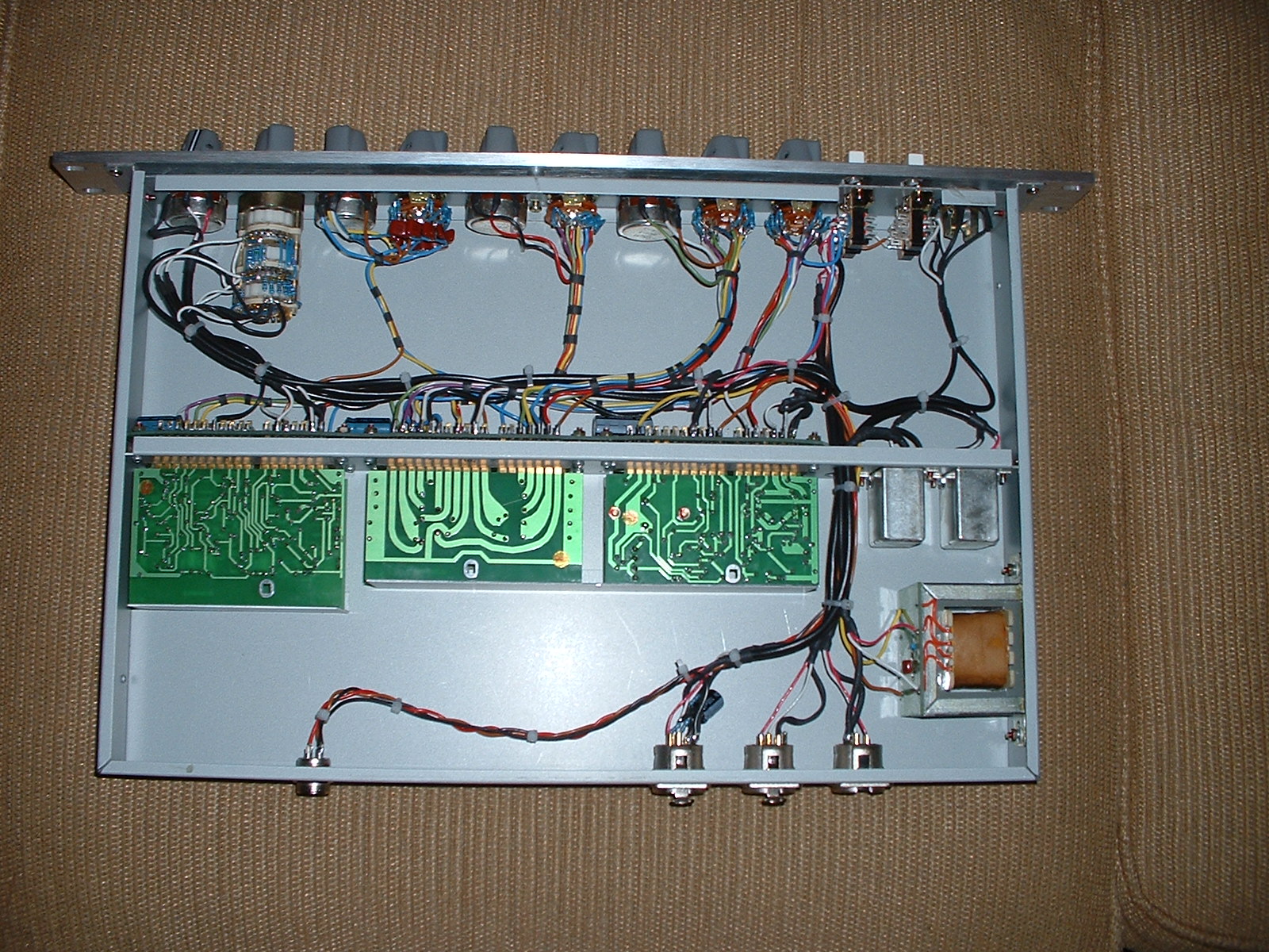
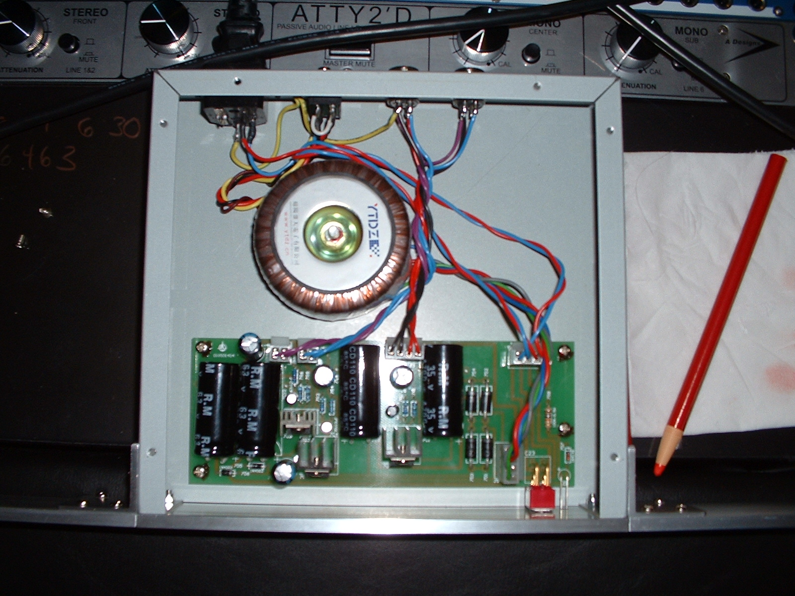
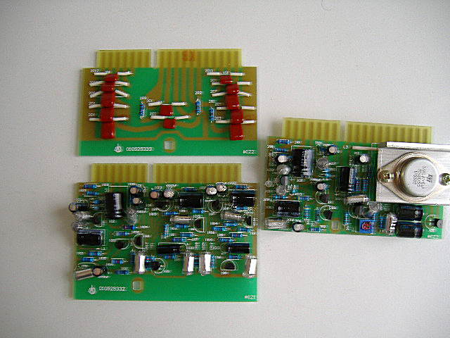
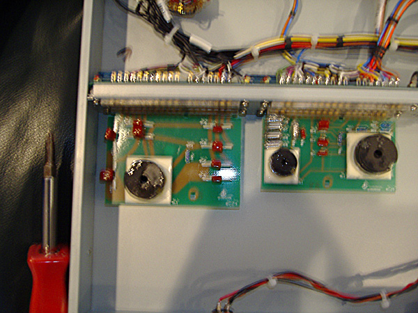
I just bought one of these things thinking I was going to take my B283 boards out of some 1272's I have swap out the transfromers and I'd have basically the sound of a 1073 for way less money. Only one problem the cards aren't exactly interchangable as some have suggested including the U.S. distributor. I asked for a copy of the schematics but they didn't seem inclined. The boards are extremely close just different enough to make life tough. Any ideas? The Chameleon is very well built they just dropped the ball on a couple of things like no tantalum capacitors, I suspect the transformers are weak etc..
 
Can you trace the circuits on the cards?  They're probably quite close, if not exact (with additional frequencies, of course), although the component layouts may be a bit different.  I'd think it shouldn't be too hard to trace them out, however, using original Neve schematics.  I doubt they strayed much from the original design.

I'd think replacing the transformers with originals (or Carnhills) and replacing the electrolytics that should be tants with tants and closing it back up would probably do it.

Also, check the grounding scheme of the thing (some actual well-known Neve cloners still screw this up).  Audio ground and chassis ground should connect ONLY in one place, preferably the AC inlet ground pin.  The transformer cores should connect to chassis while the rest of the audio circuits should ground to audio ground only.

JC
 
are there any inside pics of the 7602 ?
... just for perspective


from the manual
Output:
Balanced and floating to feed a 600 ohm load.
Maximum output +26 dBm into 600 ohms, or +20dBm into
150 ohms.
Output impedance:
600 ohms, balanced (source impedance 75 ohms).
Frequency Response:
11 Hz – 77.65 kHz – 3 dB.
Level variation is less than 0.2%.
Distortion:
1k Hz = 0.0245%
All tests results were measured using a Stanford Research
Model SR780 signal analyzer and a Fluke 8060a.
Input signal was 1v rms input signal and 20dbu output
signal.


... it has an external power supply ?

again from the manual
Pin 4 is Audio Ground (shield)
Pin 3 is +48 Volts D.C.
Pin 2 is +24 Volts D.C.
Pin 1 is -24 Volts D.C.

Pin 1 is not shield but -24volts or is it ... ?
err ...
:?
or is it just early on a Sunday morning ?
 
It does have an external power supply and I wondered the same thing, why-24v? But I checked pin 1 and once it reaches the unit it just floats, maybe they plan on using the same power supply for up and comming equipment?
I'm trying to trace the circuit right now, the edge connector is different and it looks like connector 'N' is missing on their design. It does use a 2N3055 output transistor so I think I'm just gona try putting in tantalum capacitors and change the transformers instead of taking chances or taking too much time tracing the board.
I'll try an post some pictures in a little while.
 
Is it possible that this is a commercial switch mode unit that just happens to have +24 and -24
and this is where the +48 volts comes from
or
is there 3 genuine independent outputs ?
:roll:
there is 24 volt relays inside ... ?
:oops:
errr
wot was the question !?

YES pictures please ... :green:
 
It looks like just a standard powersupply with a toroidal transformer and three seperate outputs of -24V, +24V and +48V only the -24V doesn't get used. I don't see any relays everything is done in the powersupply box and there's 3 seperate regulators, so DC into the pre amp box. I'm pretty sure they designed it like this with the intent of using the same power supply for future products requiring bi-polar supply. And what might be cool is they sell the power supply for $100 dollars seperately in a nice rackspace could be used for other projects if you didn't want to take the time.


I have pictures in jpg. form how do I post them?
 
there is a free picture posting site
coppermine ?? something like that

OR
you can send to one of us that runs a web site
I can do it ... or who ever you feel comfortable communicating with
 
In case you don't trust the Australian you can mail it to me as well @ matt(at)matt-allison(dot)com (replace the () with the correct characters) and I'll be happy to host them (I've 2GB's of space and host afew other forums guys stuff)

(P.S Kev, I'm just kidding, I'm a dual citizen of South Africa, and would you believe. Australia! Passport and all :green: )

Matt
 
[quote author="matta"]In case you don't trust the Australian you can .... [/quote]
lol ..... :green:

yeah bloody ozzie bastards
always getting in people's faces
don't trust 'em
:twisted:
 
Hah hah,

Yeah those convicts never did anyone any good, LOL!!!! Not to go off topic but I really do have a Aussie passport and I travel on it pretty much anywhere except the UK and South Africa. Sir Robert Torrens who instated the Torrens Deed was a family relative and for his service the Queen of England gave us citizenship to Australia, your weird triva for the day...

Looking forward to seeing the Chameleon pics.

Matt
 
Hey Guys,

Here are the pics. Rich any chance of a shot of the component side of the actual unit? I want to see the quality of the components that went into it.

CM_7602.jpg


CM_PSU.jpg


Cheers

Matt
 
coool :cool:
that fake BA283 card is near what I had planned for the Group DIY Project 1

it may still happen

the object was to have a recognisable layout of the 283 including the TO3 but instead of the edge connector
a row of screw terminals
and four mounting holes for bottom plate mounting with stand-offs

easy DIY and clearly showing it's inspiration
add the various upgrades like the JLMswitchKit etc and you can 1272, 1290 and so on.

swap the tants ands polystyrenes and decide for yourself what is going on.

as I said
it may still happen
 
nice pics... I also thought of buying a chameleon pair..

that one looks very close to the chandler 1073 clone

the cableing is not so nice, and the transformers should be replaced..

but what about those red mylar (metalized plypropylene) caps?
are they ok, or should they also be changed to better types?


@rascal: where can I get 2n3055 from "ON"
 
I think those red film caps are Panasonic V Series. Excellent caps! But not a good substitute for what was originally used.

I agree that the ST 2N3055 sucks, but an On Semi will not sound the same as an old Motorolla either. I've swapped Motorollas from original 283 cards and the high end/upper mids are much softer. Maybe that's just from aging p-n junction? I don't know. Aside from Motorolla, I've also seen Newmarket 2N3055 in old N cards, FWIW.

Electrolytics: Do I see some light blue Xicons hanging off the edge connectors? Probably the worst axial cap known to audio. What are all those radial black ones?

Resistors: Nice of them to use half watts everywhere. Are those %1? %2 metal films with a loser temp coeficient like +/-100ppm or worse would be closer to what N used... not that you really wanna go there. I'm just being a dick. :wink:
 

Latest posts

Back
Top