Momentary Pushbuttons - conversion to Latching?

GroupDIY Audio Forum

Help Support GroupDIY Audio Forum:

This site may earn a commission from merchant affiliate links, including eBay, Amazon, and others.
G

Guest

Guest
I have a load of Monentary EAO pushbuttons from an Alice Braodcast desk
I normally only ever use Latching ones

As more momentarys are very very cheap (on clearance at Canford)
What can I use these for - the only thign I can think of is Talkaback
As I am a sole performer and record myself - Talkback is not really an ideal option for me?

ANy other ideas guys?
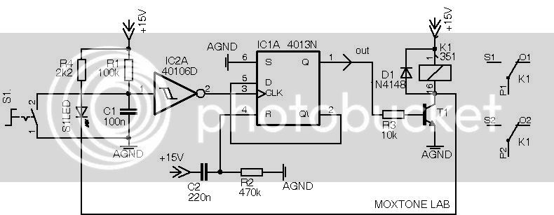
Can I use these with some sort of relay circuit to convert to a Latching circuit?
 
Debounce the signal from a momentary switch closure (lowpass a bit and then sharpen with a schmitt trigger) and use to toggle a D-flipflop (drive the clock input with your processed signal and tie Q bar to D).

There's also a scheme where two inverters are tied together like snakes biting their tails. An R from one inverter output goes to a C to ground. The R-C junction gets connected with your momentary switch to that inverter's input. This toggles the state of the system.

You can use the flipflop outputs or the inverter outputs to drive a relay (with a suitable driver depending on the relay coil) if you can't just use the d.c. voltages to control what you want directly.
 
Thanks...
On first reading it's a bit double dutch to me..
However I am very familiar with software flip flops - and just reread it and I can actually think I know whats going on.
Now off to find information

Thanks for the pointer

regards
Simon
 
Hey Simon,
Do you know if Canford still have them on sale? i browsed the clearance online catalogue but i can't seem to find them.
 
"One of six"

switch.jpg
 
[quote author="kruz"]Hey Simon,
Do you know if Canford still have them on sale? i browsed the clearance online catalogue but i can't seem to find them.[/quote]
http://www.canford.co.uk/commerce/cheapitems/specialoffers.aspx
Only the three and four element ones (eg 3PST, 4PST) non latching
 
Moamps
Whooah - many thanks - well above and beyond the call
I even understand it ..
Just a few things to ease my lack of knowledge..

The feed from the IC Qn to the Relay Drivers - these just go to the coild don't they (like a normal SPST circuit)

I take it you don;t have to use all the D inputs (if you have less pushbuttons)
 
[quote author="uk03878"]
The feed from the IC Qn to the Relay Drivers - these just go to the coild don't they (like a normal SPST circuit)[/quote]

Hi,
CMOS isn't capable to drive the relay directly.
You may use the transistor (picture below) or special driver ICs (ULN 2803 etc.)
I take it you don;t have to use all the D inputs (if you have less pushbuttons)

Of course.

Regards,
Milan

driver.jpg
 
I think moamps's circuit only latches---once. If you want things to ever unlatch you will have to generate a low-going reset pulse at pin 1.

I assumed that the mechanically latching switch you are wanting to emulate was push-to-latch, push-again-to-unlatch, i.e., a toggling function.

If what you want is push-once-latch-forever (until the whole six are reset) then it will probably be o.k., although I would feel more comfortable if there was a bit of debounce delay in the wired-OR drive of pin 9.
 
[quote author="bcarso"]I think moamps's circuit only latches---once. If you want things to ever unlatch you will have to generate a low-going reset pulse at pin 1.

I assumed that the mechanically latching switch you are wanting to emulate was push-to-latch, push-again-to-unlatch, i.e., a toggling function.

If what you want is push-once-latch-forever (until the whole six are reset) then it will probably be o.k., although I would feel more comfortable if there was a bit of debounce delay in the wired-OR drive of pin 9.[/quote]
Yep - toggling was what I was after
And if I feed the light in the relay circuit I can get everything a latchign button can do (with the excpetion of it physically appearing IN and a audible click)
 
[quote author="bcarso"]I think moamps's circuit only latches---once. If you want things to ever unlatch you will have to generate a low-going reset pulse at pin 1.[/quote]
Hi,
it's interlocking "one of six" selector.
although I would feel more comfortable if there was a bit of debounce delay in the wired-OR drive of pin 9.

I find it not neccessery.
I assumed that the mechanically latching switch you are wanting to emulate was push-to-latch, push-again-to-unlatch

Here you are. ;)
TOGGLESWITCH.jpg
 
Ah yes you did say "one of six" which indeed it (your first circuit) is. Let's see though---if I press one and hold it down while pressing another, then the clock nevers has another transition so initially it's the first one that gets latched? But then it's the last released, if there is any contact bounce, that stays latched I guess. Under some very rare conditions you could in principle latch more than one if pressed and released truly simultaneously, but the likelihood is negligible. So it has more-than-one lockout for all practical purposes.

And of course the second is about what I described in my first suggestion---thanks for drawing the schematic. You have also thoughtfully provided
a power-on initialization pulse at IC1A pin 4.
 
Well, one sw to latch (power to coil) , and one to un latch.
Don't know itf thats what he had in mind.

Do you really want to see one of my schematics?
 
Back
Top