Finally racked my [email protected] to GRP DIY

GroupDIY Audio Forum

Help Support GroupDIY Audio Forum:

This site may earn a commission from merchant affiliate links, including eBay, Amazon, and others.

guavatone

Well-known member
Joined
May 21, 2005
Messages
1,608
Location
USA
I finally finished racking my AM-16 with consecutive serials. A special thanks to Joe of JLM and all the other good folks especially in setting up the relay to work with the led switches. It was a big step up from my first attempt at racking gear - I have 4 audix pres in a wooden box with a PSU in an external ammo case. This is def. the Midlantic case I buy. I didn't bake the fp too so it chipped alot when tightenning bolts.


AM16-top.jpg


AM16-fr.jpg


The funny thing with the variable pad sugested by JLM is that it seems to cut signal drastically when turned counter-clockwise.
 
Yeah, but more is more!

I had that case and felt it would be easier for my fist case to DIY with more room. This made things easier since I didn't know how I was gonna hold them down and when I thought I was don't I had to go back and resolder the AM16 connectors.
 
The funny thing with the variable pad sugested by JLM is that it seems to cut signal drastically when turned counter-clockwise.

You prob, wired it that way. Joe's pads seems to be that when fully CCW the pad is engaged, if you want it to act more like a volume pot you need to wire it the other way, like I've done on my Spectra Sonics, which uses Joe's Variable Pad Idea.

Matt
 
[quote author="matta"] if you want it to act more like a volume pot you need to wire it the other way, like I've done on my Spectra Sonics, which uses Joe's Variable Pad Idea.

Matt[/quote]

What other way? I used this with a 150Ohm res. and 1k pot


Variable%2020dB%20PAD.gif
 
Which leg did you strap the resistor across?

If you strap it across one side, the pad is FULLY engaged when fully CCW, so as you turn the pot from CW to CCW you are engaging the PAD.

Wiring the straping resistor on the other leg work like a volume pot, so when fully CCW the PAD is engaged and then DECREASES as you turn the pot CW with the PAD disengaged when fully CW.

Hope that helps.

Matt
 
If there is a lot of hum, you can bring those output jacks up with the input jacks.

You have a pretty big ƒΔ B there.

Whatever that means, I was just trying to be cool with the html set.
How's that look on your screen?
Ever seen the Lab on a different monitor? It looks totally different depending on whose computer you are on.
 
[quote author="matta"]If you strap it across one side, the pad is FULLY engaged when fully CCW, so as you turn the pot from CW to CCW you are engaging the PAD.

Wiring the straping resistor on the other leg work like a volume pot, so when fully CCW the PAD is engaged and then DECREASES as you turn the pot CW with the PAD disengaged when fully CW.

Hope that helps.

Matt[/quote]

IOC... you're just talking strictly about directionality of rotation. I was overcomplicating it....I guess that's why I'm here hehe
 
Hah Hah,

Sorry if it seemed like I was over complicating it. I hope it is clear now. Depending on which side you add the strapping resistor (150R) will depend on when the PAD is engaged, or disengaged.

So if yours is getting quieter when fully CW, then change the 150R to the other side of the pot for it to act more like a volume pot, with it getting louder as you turn clockwise.

Cheers

Matt
 
What I was refering to was the steep roll-off of signal once the pad is engaged a small amount. I wonder if there is a way to taper it differently.
 
The PAD should be fully out off circuit when turned fully CCW with only a 2k+ load left across the balanced input.

You do have the GO between before the variable pad and the variable pad going straight to the AM16 input?

Also you haven't wired the input transformer center tap to ground? As it should be left floating or it will make the PAD drop in level as soon as it is moved of the CCW position and affect the 48v phantom power as well.

Let me know what resistor value you are using at the end of the variable pad and I will have a look at what is going on.
 
Joe, the res is 100 Ohm.

The go Between ie before pad/pot then to AM16. And I rewired the am16 connectors so the shields are to 0V at HKP point. the CTs are strapped according to the manual for 600:600 with nothing on them. just J on am16s are wired to chassis star point.

I thought there was continuitly between 0V and chassis grount but it turned out to be just 10 OHMs between them from the PSU's wiring. -so that seems to be correct.
 
[quote author="CJ"]If there is a lot of hum, you can bring those output jacks up with the input jacks..[/quote]

I sm not sure why u are saying this CJ? You mean phisically right?


I just had my first full-on session with these and used them for Overheads with LDCs. so far I think they are pretty warm and clear. I may be able to live with the steep curve of the PAD but for more "delicate" situations it may be nice to have more control. I feel at some point I may want to put a piece of metal between the XFMRs and the PSU to bring the noise floor down a bit. Sounds like EMI.

Thanks for everyones help and patience.
 
Am I the only person who sees the JLM pad offered here as having potentially serious common mode rejection issues? This is a fairly standard method in vintage systems for bridging line level signals. I think you only maintain good common mode rejection with perfect pots, which don't exist. You might do it with stepped attenuators. In practice, of course, you may not have a problem with this circuit in individual applications. The reason that 0.1% resistors are specified for phantom power feeds applies in this case too.
 
Am I the only person who sees the JLM pad offered here as having potentially serious common mode rejection issues?

Variable%2020dB%20PAD.gif


We have been over this several times before. There is no CMR problem when this type of pad feeds a floating transformer input like it is shown. The pad can attually be made with only a single pot in one leg of the balanced line like lots of vintage gear as matching the resistors will do nothing as shown below. We only use a dual pot as it makes the wiring easier.

Variable%2020dB%20PADCMR.gif


As the CMR version of the circuit shows there is no circuit except for some capacitive element which is in series with some of the inductance of the primary and balancing any resistance is irrelivent as they just form one series resistance.
 
Okay. Trying to get my head around what you are saying here. This should reveal some of what I do and do not know. I know this is fine in practice (and in my head) with floating transformer coupled line level sources having T pads between them, I'm just not quite seeing this clear for mics and mic levels.

I'm curious why so many app notes go on about the importance of 1% matched resistors for balanced mic pads. Certainly they are not thinking about center tapped transformers, since they went out of fashion long before the common use of U pads for mics.

Disregarding the impedance matching situation (vs. bridging) then, are we to assume there's no balancing issue with the billions of antique remote mixers which use T pads on mic inputs in front of a floating transformer? No increase in issues related to differing series resistance in a low-level line?

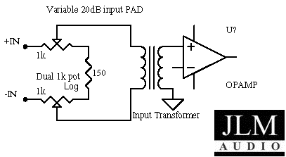
Also, disregarding balance, if we put a true 150 ohm mic on this pad, with it set at the halfway point, we get (2 x) 1150 ohms in parallel at the wipers, or 575 ohms loading the transformer primary (415 ohms reflected to the mic, assuming a true 1500 ohms from the transformer(?)) that wants to see 150-200 ohms for proper Fi. (I realize it's more complicated than that; please explain how, if possible, for the benefit of all. Or point out where it's already discussed.) We only get near 150 ohms to the transformer at close to full on, or full off, and 140 ohms at full on and off. This will probably be fine with some modern transformers, but will probably have noticable sonic affectations with many retro-fitted vintage types. This must assume a secondary load rather than a classic unloaded situation. Again, please point out where I'm wrong, so I can correct my understanding.

This is an over-simplified version of the issues too, since a 150 ohm mic on a transformer will have a different loading effect than a 150 ohm resistor on the transformers performance. The whole point of the U pad made with fixed resistors seems to be maintenance of the 150 load on the transformer primary, and the 1200-1500ish bridging load on the mic.

Someone please point out where this has been discussed before; I've not spotted it yet.

Seeing triple, time for sleep.......maybe I'll wake up and understand the error in my thinking. And nuke this post....

Thanks,
 
Back
Top