Soundcraft Venue - Peak LED stuck on red!

GroupDIY Audio Forum

Help Support GroupDIY Audio Forum:

This site may earn a commission from merchant affiliate links, including eBay, Amazon, and others.

GLRecordings

New member
Joined
Apr 18, 2006
Messages
4
Location
Denmark
Hello,
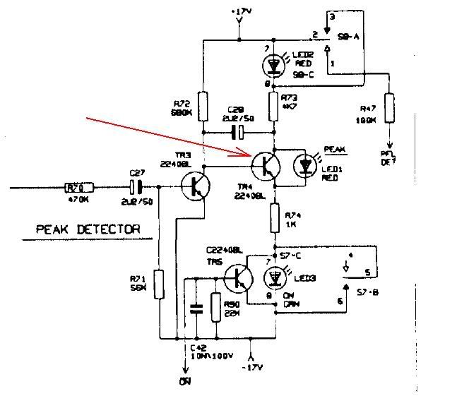
I have a Soundcraft Venue board in for general renovation. It needs a lot of cleaning and I can handle that. However, on two of the strips the Peak LED are stuck lighting red all the time. There is absolutely nothing wrong the function of the strips - everything works. Gains are fine sounds good and distorts when turned way up - but continuous 1.88v on LED.
Since there are 2 strips with the same problem I figured that somebody might have seen the same behavior and knows just what to look at. I thought it might be a cap but it turned out not to be it - at least not that one!

Any ideas anybody?

Thanks much,
Greg
 
You might want to check the TR4 and surrounding components.

venue.jpg


Regards,
Milan
 
[quote author="moamps"]You might want to check the TR4 and surrounding components.[/quote]

First a 1000 thanks for posting the schematics that fast - that was a big help.

It turned out not to be the TR4 but R72 - simply an open resistor - on both channel strips. Very strange but now it is fixed.

Thanks again,
Greg
Lydmuren.dk
 
Hi

      I have a problem with the same circuit posted above on my Soundcraft Venue 2 desk, only, a slightly different problem.

When I turn the gain knob and reach the point where the red PEAK (led1) should start to indicate a peak,  red PEAK (led1) does not come on at all and my  green ON (led3) starts to dim and eventually goes off. The same behavior is exhibit by the red PFL (led2) which if engaged, goes off in "sync" with  green ON (led3). The sound and all other functions of the ch. are OK.

I've tested  all the components in the circuit and all seem to be fine, (transistors TR3 and TR4 removed from the pcb  and tested OK with Atlas DCA 55,  TR5 not tested). All caps are new, Nichicon UPW, orientation  and value OK. red PEAK (led1) tested OK.

Any help  very much appreciated
 
syn said:
Hi

      I have a problem with the same circuit posted above on my Soundcraft Venue 2 desk, only, a slightly different problem.

When I turn the gain knob and reach the point where the red PEAK (led1) should start to indicate a peak,  red PEAK (led1) does not come on at all and my  green ON (led3) starts to dim and eventually goes off. The same behavior is exhibit by the red PFL (led2) which if engaged, goes off in "sync" with  green ON (led3). The sound and all other functions of the ch. are OK.

I've tested  all the components in the circuit and all seem to be fine, (transistors TR3 and TR4 removed from the pcb  and tested OK with Atlas DCA 55,  TR5 not tested). All caps are new, Nichicon UPW, orientation  and value OK. red PEAK (led1) tested OK.

Any help  very much appreciated
Although you said LED 1 tested OK, I would suspect it. hav eyou tried replacing it?
 
syn said:
Hi

      I have a problem with the same circuit posted above on my Soundcraft Venue 2 desk, only, a slightly different problem.

When I turn the gain knob and reach the point where the red PEAK (led1) should start to indicate a peak,  red PEAK (led1) does not come on at all and my  green ON (led3) starts to dim and eventually goes off. The same behavior is exhibit by the red PFL (led2) which if engaged, goes off in "sync" with  green ON (led3). The sound and all other functions of the ch. are OK.

I've tested  all the components in the circuit and all seem to be fine, (transistors TR3 and TR4 removed from the pcb  and tested OK with Atlas DCA 55,  TR5 not tested). All caps are new, Nichicon UPW, orientation  and value OK. red PEAK (led1) tested OK.

Any help  very much appreciated
Pretty simple circuit...

does red LED light full on with TR4 removed. If no, the LED is faulty.

If LED is good but TR4 refuses to cut off perhaps TR4 is shorted collector-emitter, or TR3 is not turning on hard enough to suck the base drive out of TR4.

The fact that you see the green LEDs dimming from hot signals suggests that perhaps TR3 is OK.

JR
 
abbey road d enfer said:
Although you said LED 1 tested OK, I would suspect it. hav eyou tried replacing it?

Thank you, abbey road d enfer. No I haven't tried replacing it. I tested LED 1 with my multimeter, it lights OK so I assumed it is OK.
Could it still be broken?
 
JohnRoberts said:
Pretty simple circuit...

does red LED light full on with TR4 removed. If no, the LED is faulty.

If LED is good but TR4 refuses to cut off perhaps TR4 is shorted collector-emitter, or TR3 is not turning on hard enough to suck the base drive out of TR4.

The fact that you see the green LEDs dimming from hot signals suggests that perhaps TR3 is OK.

JR

Thank you JohnRoberts, I'll test all the above. I measured EBC voltages in respect to GND on TR3 and TR4  and with no signal present they are spot on -  compared to working channel.
 
Hi

        no progress. If I remove TR4 the red  red LED light stays full on, so red LED is OK.
TR4 is not shorted collector-emitter, checked and rechecked.

Any other ideas?

Thanks
 
Caps are brand new and tested, OK.

I just found out that TR5 is shorted collector-emitter, could that be the problem ?
Have not checked TR5 up to now as green LED is  OK
 
syn said:
Hi

        no progress. If I remove TR4 the red  red LED light stays full on, so red LED is OK.
TR4 is not shorted collector-emitter, checked and rechecked.
OK next test is to momentarily jumper base of TR4 to -17V, effectively simulating TR3 turned hard on..

If that works (LED lights), next test is to inject current into base of TR3 (say a 20k R from +17V

This isn't rocket science, either a bad component, or bad solder joint. 

JR
Any other ideas?

Thanks
 
Solved!!! It was  bad solder joint(s) . I had this exact same problem on 5 channels. The red LED in question looked like it has solid connection to the PCB but actually it had not. It was completely detached from the PCB, both legs. Still, it stood firmly in its place held by the metal work. Thanks a lot, I learned a bunch on  how to test these kind of circuits.
 
Back
Top