JLM Baby Animal

GroupDIY Audio Forum

Help Support GroupDIY Audio Forum:

This site may earn a commission from merchant affiliate links, including eBay, Amazon, and others.

jmiller

Active member
Joined
Jul 13, 2005
Messages
31
Location
L.A.
Edit 06/12/06: I thought I'd add a few relevant links to the top to help consolidate all the information regarding this project.

http://jlmaudio.com/Baby_Animal_Mic_Pre.htm- the original site contains a lot of useful information including schematics, and some very useful tables on what parts to fit with which PSU's and input transformers
Black market "preview" thread- has a lot of useful discussion about the baby animal and kinda serves as a nice general FAQ
A useful thread on metalworking/case building
The knobs, meters, lights, boxes and such meta- good info on sourcing any extras like knobs or a case, etc.
Datasheet for OPA2604 IC opamp- I used this to confirm I wasn't putting the chip in backwards. Pin configuration is on pg3.
Let me know if there are any other useful links. /Edit

------------------------------------------------------------------------------

My kits arrived yesterday, so I figured I'd start a thread. A little backround: I'm kind of a newbie, though I've done a few small mods and simple builds, I'm still kinda "flying" blind. I've been lurking here since the board was in "the old country" before it moved here, but never got around to doing anything. Now I've got the time and the need, so here I am.

One thing not included in this kit is any kind of step by step How-to. This is fine with me as it requires me to think, be inquisitive, and learn a bit in the process. Perhaps we can build that "how to" here and save Joe the trouble of 1) writing one, and 2) having to field tons of emails from newb's like me asking mundane questions, like the ones I'm about to ask!

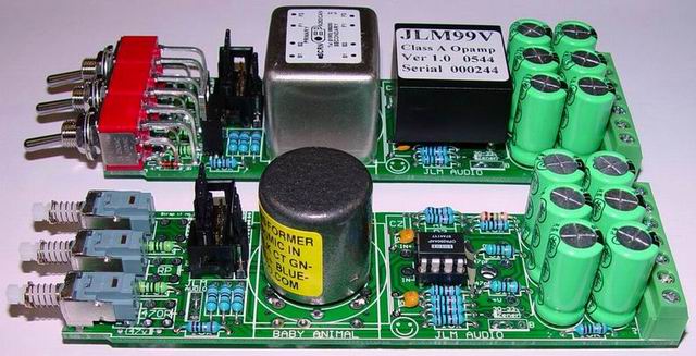
I ordered a pair of Baby Animal kits with the JLM99v opamp, the JLM 1:4 xfmr, and two DI kits. They arrived nicely packed in a little box and got here pretty fast:
unpacked.jpg


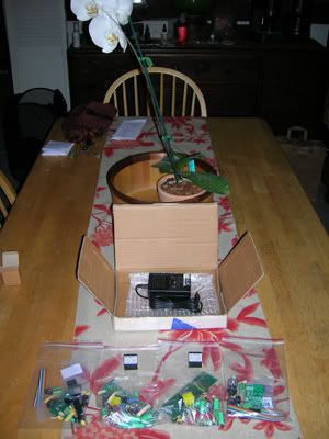
Sorry, honey, you're going to have to eat your dinner on the couch the next few days ("You mean for a change?!")... Anyways, everything seems to be of very good quality.

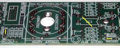
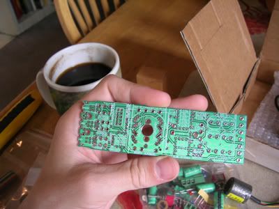
Here is the bare PCB and should give you an idea of how small they really are:
BAprePCB01.jpg


Here are a couple schematics from JLM:

Full Circuit
with JLM14 and OPA2604

Note that there aren't any specific schematics for the configuration I have, but both have plenty of info to draw from and should be sufficient. Or they would be if I didn't have my head up inside myself. So here are a couple questions:

Should I be installing the zeners, resistors, and regulators in notes 2 and 3 of the first ("full") scematic? I'm using the 48v supply here. I am of course trying to find this info myself but perhaps having it here will help others...

Here is a small capacitor and my dirty fingernails :oops: :
mysterycap.jpg


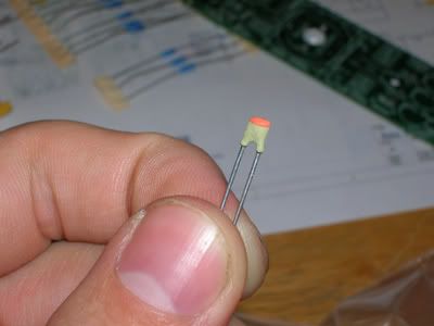
There are two of these. Are these the 0.1uf's that mount near the opamp? I've been trying to look it up but there are no other markings, and I cannot even tell what color that is.

Anyhow, I finished the DI's this afternoon:
DIscomplete.jpg


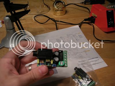
I figured I'd start on these to brush up and since they are less expensive if I blow it. Can't wait to try them. They went together quite nicely.

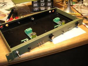
Now my biggest dilemma is whether to put them temporarily in a surplus rack enclosure I've got laying around (while I wait for the JLM ones to come out) or try a nice permanent enclosure. I'm thinking it would be good to get accustomed to metalworking.

That's enough thinking for one day. Let's Party!
LetsParty.jpg


:cool:[/i]
 
Thanks, I'm looking forward to seeing how this thread pans out. I see a couple of channels of the baby animal in my DIY future.

Cheers

Nick
 
Nice thread !!!

I don't think I see myself getting any of these, but that's only because I have several single opamp type preamps already. But I think I can help out a little with your question. I'd guess those two small caps are ceramic, used for high frequency stability. If you take a quick look at the schematic, they're the two 47p caps going from the output to the - input of the opamps. I think Joe uses metallized polyester, so the 0.1u should be rectangular... like the one in the DI.
 
great report!

the baby animal pres look super cool. i think i may hazard an attempt at them if i ever get around to finishing my green pres. hehe.

be sure an let us know how they sound once you get them mounted.
 
Hi J

mysterycap.jpg

The cap you are holding is a 47pF k series ceramic. This has text on one side in yellow but they are hard to read at the best of times but great caps otherwise.

MonoCap.jpg

The 0.1uF mono chip cap is a yellow or blue bead type in the baby animal kit.

BAnoRegs.jpg

When running 48v power supply no reg parts are needed for the 48v phantom power rail (* parts) and if the opamp can run on 48v it also doesn't need a regulator (# parts). Just 2 wire links (BD681 C-E) need to be fitted to link out the regulators as shown in the photo above.

The link across the DIP IC between pin 4 and 7 is to pull the inverting output to ground so the output balancing will still work without a output transformer when using a JLM99v or Hybrid.

Note that there aren't any specific schematics for the configuration I have.

There is now. Link is also now on the Baby Animal web page
 
Thanks Greg and Joe for the help! I get it now. Well, sorta :razz:

Joe, I hope you do not mind me working through this here. My hope was to actually spare you the trouble of having to deal with questions like mine over and over.

You can actually see remnants of text on that cap in the picture better than you can see them with the naked eye. Does the color on top denote anything? I tried looking it up but found nothing relevant (just some stuff about old paper and mica caps).

I also see the 0.1uf cap (mine is yellow). That one actually has text on it that I should have looked up :oops: . I actually had some of that stuff printed out before but lost it.

I'm moving on to the pre's today. The DI's went together really well. I'm really excited about this kit. I'll be happy to report on them more as I continue to work on them.

[quote author="Arno"]They have Orval in LA ?? [/quote]

I don't mean to get too far off topic, but... Belgian Ales have been gaining in popularity in the US in the last few years. There are a few american breweries that try to imitate the style but I haven't been blown away by any, though Unibroue (Canadian) does some good Belgian styles.

Anyways, I'm a bit of a Belgian beer nut:
BelgianBeerNut.jpg

What you can't see is the sticker on that Chimay bottle that says "2003 Vintage"
:twisted: :twisted: :twisted:
 
Okay. Couple curiosities...

1) in the schematic, there is a 470R resistor on the phantom switch, as well as two 470R's on the Pad. Now, I've only got two 470R resistors per pre. I did notice in this pic the 470R is omitted from the phantom switch (the pre in the forefront):

Baby%20Animal%20Pre%20640.jpg


Did I accidentally eat my resistor? :oops: It looked delicious. Or are these only necessary for a >48v PSU?

2) For jumpering between pins 7&4: Can I do this by putting a jumper in the DIP socket? Having the socket installed seems useful to me, and i COULD solder the jumper on the back, but this seems easier. When I tried it out, the jumper (a clipped lead) fit nice and snug.

Other than that, i've got the first pre pretty much assembled. Still gotta decide on an enclosure.
 
Joe, I hope you do not mind me working through this here. My hope was to actually spare you the trouble of having to deal with questions like mine over and over.

No sounds good to me as there are so many possible combinations on the Baby Animal PCB it should help heaps to have this thread. If everyone building Baby Animal just posts on this thread with questions it will save me many emails which is a good thing and I will be notified as soon as they post and I will try to respond ASAP.

1) in the schematic, there is a 470R resistor on the phantom switch, as well as two 470R's on the Pad. Now, I've only got two 470R resistors per pre.

I was about to blame Matt for packing the kits wrong :wink:. But I just checked and I stuffed up the part list. So you are right you are 1 x 470R short. :oops:

All baby Animal kits posted before today's date will be one 470R short. Parts list now updated. Thanks J. Let me know if you need me to post you the resistor or if you find any other bits that don't add up.

I did notice in this pic the 470R is omitted from the phantom switch (the pre in the forefront):

When using the pushbutton Switches the 470R for the phantom power and RP have to be mounted on the opposite side of the PCB to the switches.

For jumpering between pins 7&4: Can I do this by putting a jumper in the DIP socket? Having the socket installed seems useful to me, and i COULD solder the jumper on the back, but this seems easier. When I tried it out, the jumper (a clipped lead) fit nice and snug.

Either way sounds like good idea to me.
 
[quote author="JLM Audio"]
I was about to blame Matt for packing the kits wrong :wink:. But I just checked and I stuffed up the part list. So you are right you are 1 x 470R short. :oops:

All baby Animal kits posted before today's date will be one 470R short. Parts list now updated. Thanks J. Let me know if you need me to post you the resistor or if you find any other bits that don't add up.[/quote]

Heh. I'll see if I can find a couple tomorrow. No worries! Everything else is good.

When using the pushbutton Switches the 470R for the phantom power and RP have to be mounted on the opposite side of the PCB to the switches.

I thought about that and then forgot :oops:

Other than that everything is great I think!
 
Ok, I'm back more quessy's.

Thanks Joe, for setting me straight with the .1uf cap. (if it's useful to anyone else, Joe said it's better to use the ceramic bead type rather than a poly here)I've found i can get the bead type from jaycar, but they're only rated at 50v. Do i need to find one thats up more around 63v? The zener I'm using is a 33v 0.5w. I can get higher rated caps when i do my next order from RS, but i only need two, and they're cheap as chips from jaycar.

How do you figure out what voltage a cap should be from the voltage in your curcuit? I have seen it around here somewhere? but is there some sort of formula? I'm thinking a 50v cap should be sweet for 33v, right? Would it need to higher for the 47v? I had a quick look at the schem, and to me(this could be horibbly wrong) it looks like the 0.1uf is interacting with the 30-47v zener and not the 47v used for phantom power.

Anyway, I like how this is making me actually think about whats goin on in the curcuit more than kits do. I love the kits tho!! It's just good to learn about what the crucit's actually doing rather than being stuck with the"Well I can solder pretty good" kinda ignorance I still have. the tranno's and loading thing will be good for that too.

And where's the rest of you crazy DIYers who were foaming at the mouth over these not too long ago? Lets see some completed and varying versions!! :green: :thumb:


Steve
 
Good pics. The project is a tad too paint-by-the-numbers to my tastes. but at least you know it'll work and sound good. (but where's the fun in that?) :thumb:
 
I've found I can get the bead type from jaycar, but they're only rated at 50v

The 0.1uF 50v bead cap only has half the 48v to 62v power supply volts across it so 50v type is fine.

it looks like the 0.1uf is interacting with the 30-47v zener and not the 47v used for phantom power.

No it is just high frequency smoothing for the half voltage rail.

The zener I'm using is a 33v 0.5w

The Darlington transistor regulators are designed to work with 400mW or 500mW type zeners. But you can use 1watt types if there legs are small enough to fit the PCB pad holes. If you are using a 33v zener I gather you are using a NE5532 or 2520 etc for the opamp. Also because you are using a 48v power supply you only need to fit the opamp regulator.

How do you figure out what voltage a cap should be from the voltage in your circuit?

If using the 48v Power supply then all electro caps are 470uF 50v. If using the 62v power supply one cap on the PCB needs to be 330uF 63v instead of 470uF 50v. All this info is screen printed on the PCB. All electro caps need to be 10mm diameter to fit on the PCB.

Let me know what Cinemag transformer and opamp you are going to use and I will be able to help you work out RL,CL,RZ,CZ,RP,RG :grin:

Thanks
 
Almost done! I found a few 470R resistors. Board were finished yesterday afternoon. Today I worked on the case, which was kinda tricky for me, but I think I did alright.

I had an old, scratched up generic rack enclosure lying around that apparently was part of the phantom power supply for my old boss's console. He let me have it a long time ago, and I knew it'd come in handy.

The biggest problem with using this case was how beat up it looked. After thinking about it, I headed to Autozone and bought a can of olive colored autobody primer. It covers up the scratches and gives the rack a cool military look:

Primeredrack1.jpg


I kinda like the military look anyway, and was a cinch to do. It isn't luxurious, but at least it looks like I yanked it out of a jeep or huey instead of a junkheap in the garage. I also figure I can print text on it with stencil and it will still look neat in it's own way, and fit with the overall look.

All that's left is wiring. I've pretty much got it figured out, but I'm not quite sure how to wire up the power/switch. Also, I just couldn't find any bits or punches for the XLR jacks. So, I'm wondering if there's any reason I can't just leave "pigtail" connectors hangin out the back? I'm thinking just a couple inches of cable fed through some rubber grommets with mic cable style XLR connectors hanging off them. It sure would save me a lot of trouble. Other than that, this thing is about to have life :)
 
I'm not quite sure how to wire up the power/switch

Just need to run the +48v from the SMPS socket to the power switch and then from the power switch to the two 48v terminals on the baby Animal PCB. 0v from SMPS just wires to all 0v points. If you need a power LED use a 10k resistor in series with the LED.
 
Let me know what Cinemag transformer and opamp you are going to use and I will be able to help you work out RL,CL,RZ,CZ,RP,RG

Hi Joe,

In keeping with the above post may I make a suggestion? Why not offer some of the more popular combinations here so guys can try them, and re-edit the post as and when you work out more combinations.

The first likely candidates would be the ones you are selling as kits:

IC Opamps
OPA2604 Opamp and JLM14 input transformer
OPA2604 Opamp and OEP262A3C input transformer

Discrete Opamps
JLM99V Opamp and JLM14 input transformer
JLM99V Opamp and OEP262A3C input transformer
JLM Hybrid Opamp and JLM14 input transformer

I also have some suggestions for a few others opamps and transformers to create 'STYLED' type pres:

Discrete Opamps (STYLED COMBO's)
JH 990 Opamp and Jensen JT-16-B input transformer (John Hardy M1)
FF JFET-993 Opamp and Lundahl LL1538 input transformer (Millennia/Forsell Tech)
2520 Opamp and Cinemag CM-75101APC input transformer (API 312)

I know the 'Animal Pre' is not a clone and none of the above combination will in any way 'copy' them so that why I called them styled pres, drawing on them for inspiration.

Cheers

Matt
 

Latest posts

Back
Top