Altec 'coke bottle' output trannie?

GroupDIY Audio Forum

Help Support GroupDIY Audio Forum:

This site may earn a commission from merchant affiliate links, including eBay, Amazon, and others.

gang of elk

Well-known member
Joined
Jun 16, 2004
Messages
257
Location
tn, usa
AltecP518aSchem.jpg


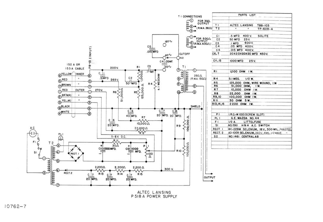
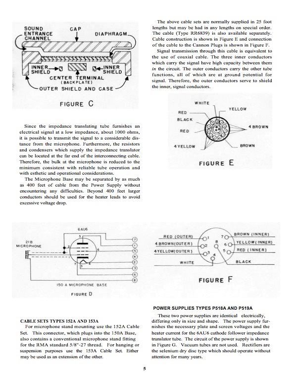
any ideas on a modern replacement for T1? As you can see the mic's output trannie is housed in the PSU.

The 6AU6 in the mic body provides signal at about 1000 ohms, which I think comes in on pin 6 to the PSU. looking at the PSU schematic, there's lots going on before that signal hits T1, so not sure what T1's primary should be.
 
The values of C3, C4 and C5 and the cutoff frequencies given will tell you the primary inductance, albeit indirectly. As for ratio, the source and load impedances can get you in the right ballpark. Are you sure the source impedance from the tube is only 1K? That's very low. I don't know the conditions since you didn't link the schematic for the "head."
 
AltecM11body.jpg


Thanks Dave. I should have mentioned, there not much in the mic body other than a 6AU6.

Above is a relevant page from the manual.
 
The 6AU6 is being operated as a pentode so the plate impedance is going to be high. This site says that the primary impedance for an Altec Peerless TBB-103 is 50K ohms and the secondaries are 38, 150 and 600 ohms. It is not clear if each of the primaries are 50K or the total is 50 so there is the possibility that the total could be 100K, a more likely value for the pentode.

http://blog.wec5.jp/?eid=178061
 
Oops! Just noticed that the tube is actually a cathode follower. The connection from the wire going to the output transformer feeding back to the suppressor grid and a shield connection and a different order of the numbers confused me. Anyway, they seem to have used a 125K in the cathode (along with the 1K bypassed by a 50uf cap ??), so I am going to assume that the tranny is set up for 100K. Hope the tranny is ok. Peerless was the best manufacturer and it appears to be huge from the photo.
 
So the 1000 ohms the manual refers to is for B+ ?

Thanks, burdij, for the clarification and info regarding TBB-103. I didn't think of searching for Peerless.

BTW, I'm missing the entire supply for this mic (nothing is broken) so I'm thinking of building from scratch. The O/P trannie is the big 'unknown' at this point.

Dave, thanks for your tip. I'll use this as an exercise to get a better understanding inductance in general.
 
[quote author="gang of elk"]So the 1000 ohms the manual refers to is for B+ ?[/quote]

No, you were right the first time, that's the output impedance of the cathode follower.

Thanks, burdij, for the clarification and info regarding TBB-103. I didn't think of searching for Peerless.

BTW, I'm missing the entire supply for this mic (nothing is broken) so I'm thinking of building from scratch. The O/P trannie is the big 'unknown' at this point.

You might try Mike LeFevre at Magnequest. He owns the Peerless name and all of the old documentation. He's usually very helpful.

To get a rough idea, and a good primer on cathode follower mics in general you could check out Dave Royer's ADK mod article .
It's based on a similar Altec cathode follower circuit (165/175) using a triode connected 5840 and a Jensen MB-D trannie.

Best of luck,
tim
 
I used a Sowter mic input transformer backwards, 7:1 turns ratio (10k impedance). That's also what Sony used for the C37A mic which also used a 6AU6 in cathode follower mode.

I like the sound of the Coke Bottle. I have also built the supplies for them - it's fairly straightforward.

-Dale
 
Thanks for all the helpful comments and info.

I'm gonna try either a Sowter 9610 (as recommended by Brian Sowter for this application)

http://www.sowter.co.uk/specs/9610.htm

or a Cinemag CM-2480

http://www.cinemag.biz/mic_output/CM-2480.pdf
 
[quote author="gang of elk"]I'm gonna try either a Sowter 9610 (as recommended by Brian Sowter for this application)

http://www.sowter.co.uk/specs/9610.htm

or a Cinemag CM-2480

http://www.cinemag.biz/mic_output/CM-2480.pdf[/quote]

Both of those transformers are 10:1, which is a way higher ratio than this mic needs. I'm not one to second guess Brian Sowter, and for a traditional plate loaded mic output those are excellent choices, but the 150A is a cathode follower mic with an already low output impedance and relatively low level.

Looking at the schematic the TBB 103 is wired as a 2:1 step-down for a 250 ohm output, with options for 1.5:1 (500ohms) and 5:1 (30 ohms). Using a 1:10 trannie backwards you'd have a 10ohm output impedance and very little signal.

2:1 would be a much more appropriate and accurate (historically) choice.

-tim
 
I just redrew the CF part of the circuit.

The power supply "floats" the fil supply at about 150VDC and has a hum balance R9,R10 going to the wiper. This would be important to do for heater to cathode breakdown voltage. All the voltages look like they need to be close to the original or untill we understand the circuit.

I am still working on understanding the finer points of the circuit

the cathode drives G2 inphase the end of the 51K via the .5uf cap C6 makes the other end of the 51k a low z node. The cathode also drives the output transformer

R1 and C2 have a DC voltage drop that seems to be how the tube is bias. NOW the AC signal from the 1K and 125K node goes to G3 and the shield around G1 wire to the capsule inphase

This makes G3 a little more - than the cathode, -1.58VDC

125k + 1K =126K

200V/126K= 1.58ma

1.58 ma across the 1K 1.58V

The capsule is charged via grid leakage current I would guess

IS it the leakage between the shield and G1 that gives a bias path for the tube? Thats what I think I "see"
 

Latest posts

Back
Top