GSSL SuperSC board

GroupDIY Audio Forum

Help Support GroupDIY Audio Forum:

This site may earn a commission from merchant affiliate links, including eBay, Amazon, and others.
hi,

if your sidechain board was designed to be used alone (with L+R summed at the input thru those two 20K), you should go for 10K.

because if you use 2 boards, it will receive half the signal it's designed for...

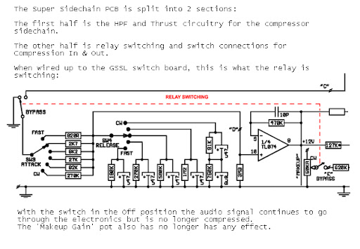
i didn't see any schemo for the barclaycon, but i see those two 20K close to the input.

but anyway :
send a signal thru the comp.
you should mesure first the input (before 20K or 10K input resistor) & then the output (just before the 47K at the output of the board) of the sidechain board when it's off.
is there a difference ?
if yes, you should change those 20K to adjust that, especially because it seems there isn't any output trimmer on your card.

note that wether the sidechain board is on or off, or in any position, it's always in the signal chain.
you can notice the difference (level drop) it make only if you disconnect it.

compression engaged or not... doesn't make a difference.

to me, changing this 20k make me get a bigger treshold range.
i don't have to go so far to the left with the pot to get compression...
ie : SLAM THE METERS HARDER WWWWWAAAAAHHHHHHHHH !!!!!!!!!!!!!!!!!!!!!!


I have been using my GSSL forever but finally today I ripped it out of the rack and installed the super sidechain board. Holy crap I don't know how I used this compressor without it. Truthfully I didn't use my GSSL a whole lot. But now that's gonna change. It's like getting a whole new compressor.

I'd like to thank everyone for such an awesome mod. I appreciate the effort that went into this. And thanks Barclaycon for having great directions on your site. I slapped it in there in no time.

I adjusted the tl and tm circuits as described on the site. Works great. But are people turning the compression up just a wee bit more than that in practice? Just wanted to see how others have tweaked that.

Thanks
John
 
Hi,

Must admit I'm a bit lost after the various versions...  ;)
can anyone tell which PCB-layout is the one that's added to Gustav GSSL-comp set ?

Bye/thanks,

  Peter
 
clintrubber said:
Hi,

Must admit I'm a bit lost after the various versions...  ;)
can anyone tell which PCB-layout is the one that's added to Gustav GSSL-comp set ?

Bye/thanks,

  Peter

This one.

http://picasaweb.google.com/barclaycon/GSSLSuperSidechainPCB#
 
Hi Guys,

I have a question regarding the SSC-Boards from Gustav, with the relays printed on.

If I want to build a GSSL with switchable oxford/GSSL-Mode (Turbo board plus 2 x SSC), do I  need to put in the relays on the SSC-Boards?
what exactly do they do?

thanks for help,
cheers,
mark 
 
If I want to build a GSSL with switchable oxford/GSSL-Mode (Turbo board plus 2 x SSC), do I  need to put in the relays on the SSC-Boards?
what exactly do they do?


this is what the relay does


Notes%201.jpg


uuups, sorry  :p
I could`t find my message in the forum after I posted it, so in my eagerness to get an answer I assumed that something was wrong...
Thanks anyway :D

Jørgen
 
Does anyone have a Mouser project/bom saved for the Barclaycon version of the Super side chain BOM? Just want to save myself the hassle of entering it all in if someone has already done it.

thanks!
 
Hi All,
 
      I'm at the point were I'm starting to connect the dots ;D  and am a little confused on the 47k resistors were the SSC is connected and I also want to add a Turbo Board.  I made this little graphic to Illustrate how I think they are to be connected. Is this correct ?
 

Attachments

  • SSL plus SSC and Turbo copy.jpg
    SSL plus SSC and Turbo copy.jpg
    68.8 KB · Views: 251
I have one of the Barclaycon SSC installed but I do not think it is working correctly. (I installed this right from the beginning so I have not tested the GSSL without it other than switching to SSC off mode).

Whenever I am compress the effects are very very subtle. If I go into TL or TL mode and adjust the trimpots I see no change on the signal. When I am in off position (i.e. default SC mode) it is still not compressing much. The meter however is showing compression and is moving, the makeup gain works too.
The only time I have gotten really significant compression (visually on the meters and audibly) is when I switched to external side chain and used a kick drum signal from a drum machine.

This makes me wonder if there is a problem with the internal audio feed of the SC circuit.  Any tips on what I should look at for debugging?
 
audiophreak said:
I'm at the point were I'm starting to connect the dots ;D  and am a little confused on the 47k resistors were the SSC is connected and I also want to add a Turbo Board.  I made this little graphic to Illustrate how I think they are to be connected. Is this correct ?
For a GSSL with TWO (2) sidechainfilterboards and a Turbo my approach would be something like this ugly scribble
I'd use a DPDT switch for the differing input resistor requirement in both scf-boards for unity gain behaviour:
- Turbo mode: a single 10K resistor (you can keep both already soldered 20K resistors when you wirelink the L+R input of this scf-board) for the upper scf-board input and both 20K for the lower scf-board which get switched in parallel by the 2nd pole of this switch).
- GSSL mode: upper scf-board and turbo not connected, lower scf-board 20K input resistors separately fed by L and R.

For a GSSL with ONE (1) sidechainfilterboard and a Turbo, same switch but you replace the upper scf-board with a 47K resistor.

Hope this making any sense.
 
intellijel said:
I have one of the Barclaycon SSC installed but I do not think it is working correctly. (I installed this right from the beginning so I have not tested the GSSL without it other than switching to SSC off mode).

Whenever I am compress the effects are very very subtle. If I go into TL or TL mode and adjust the trimpots I see no change on the signal. When I am in off position (i.e. default SC mode) it is still not compressing much. The meter however is showing compression and is moving, the makeup gain works too.
The only time I have gotten really significant compression (visually on the meters and audibly) is when I switched to external side chain and used a kick drum signal from a drum machine.

This makes me wonder if there is a problem with the internal audio feed of the SC circuit.  Any tips on what I should look at for debugging?
Is supply voltage +/-15V working on scf op-amps pin 8 and 4 ?
You feed both gssl inputs (L+R) with your audio/testsignal ?
Voltage at scf input is the same as voltage on scf output (before the 47K) when switched to scf-bypass ?
 
Is supply voltage +/-15V working on scf op-amps pin 8 and 4 ?
You feed both gssl inputs (L+R) with your audio/testsignal ?
Voltage at scf input is the same as voltage on scf output (before the 47K) when switched to scf-bypass ?

Supply is correct at both opamps (and on all other ICs on the mainboard).
I am feeding a stereo signal for the tests
Have not measured the input vs. ouput in SCF bypass yet. What point on the SCF board can I measure this at? It looks to me like the north side of the 47k?

One thing I may be doing wrong:
In the barclaycon instruction I have wired the points marked POT A on the POT B (and removed the link) on the ssl panel pcb as direct connections to the points marked POTA and POTB on the SSC. However, in the photos it looks like the wire of the POTB is going to the wiper of the Makeup gain but afaik this is the same place.


thanks!
 
intellijel said:
Is supply voltage +/-15V working on scf op-amps pin 8 and 4 ?
You feed both gssl inputs (L+R) with your audio/testsignal ?
Voltage at scf input is the same as voltage on scf output (before the 47K) when switched to scf-bypass ?

Supply is correct at both opamps (and on all other ICs on the mainboard).
I am feeding a stereo signal for the tests
Have not measured the input vs. ouput in SCF bypass yet. What point on the SCF board can I measure this at? It looks to me like the north side of the 47k?

One thing I may be doing wrong:
In the barclaycon instruction I have wired the points marked POT A on the POT B (and removed the link) on the ssl panel pcb as direct connections to the points marked POTA and POTB on the SSC. However, in the photos it looks like the wire of the POTB is going to the wiper of the Makeup gain but afaik this is the same place.


thanks!
If it works with an external sidechain, POT A+B should be wired correctly, further leading to the suspicion of a wrong feedback resistor value at the summing amp of your scf board. You surely have doublechecked, this 10K is not a 120R for real ? If you mixed up the leftmost resistor ring with the 1% tolerance ring (brown,red,black,black - brown vs. brown,black,black,red - brown), you might have read the colour code backwards, resulting in a level drop of -44dB instead of -6dB for a single ch.feed or -38dB instead of 0dB, feeding both scf inputs with the same signal.
 
I prefer to etch my own PCBs for my GSSL build... and looking for the schematic and PCB layout for the GSSL SuperSC board...
Can't find it anywhere, maybe someone can help me or send it to me by email...
thx
 
Back
Top