connect lorlin switch to PCB

GroupDIY Audio Forum

Help Support GroupDIY Audio Forum:

This site may earn a commission from merchant affiliate links, including eBay, Amazon, and others.

Robin Reumers

Active member
Joined
Jun 13, 2006
Messages
32
Location
Belgium
Hi,

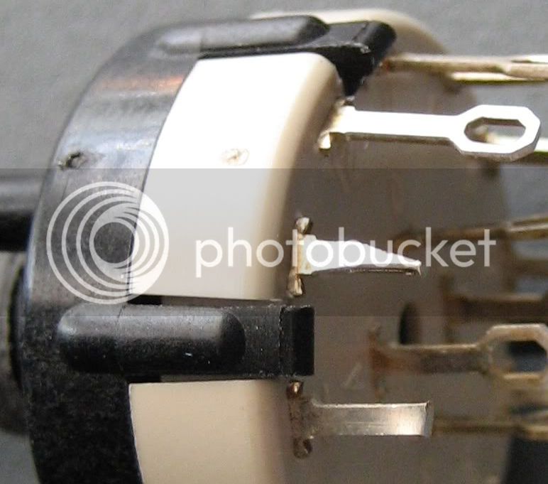
I'm working on the 1176 at the moment, but I'm wondering how I can connect the lorlin, looking like this ->http://www.matt-allison.com/diy/lorlin02.jpg
to the PCB because the holes in the PCB aren't big enough to put the switch through, can anyone explain me how to do this please?

Thanks
 
They are solder lugs - you can buy the PCB version - or snip off the solder lugs and then use a small PCB drill to enlarge the holes if needed (but be careful about loosing the solder pads on the PCB)


Nowadays I mount them off board and use wire between the solder lugs on the board
 
If you cut each lug in two directions it will fit without the need to enlarge the Pcb holes:

Lug.jpg
 
Ok thanks, that's where I was afraid of, maby I'll try to connect them with mounting wire, you think this will work, or is it easier to cut the legs?

Robin
 
It¨'s easy to cut the legs. Just cut them at the first narrow part of the solder tag and then maybe make a V-shaped cut (not too critical really) by snipping from both sides..
 

Latest posts

Back
Top