Yup, the circuit looks OK, except for signal pinning as already pointed out.
Is the +/- supply pinning OK? Can you trust the data sheet..... there is already one error :?!
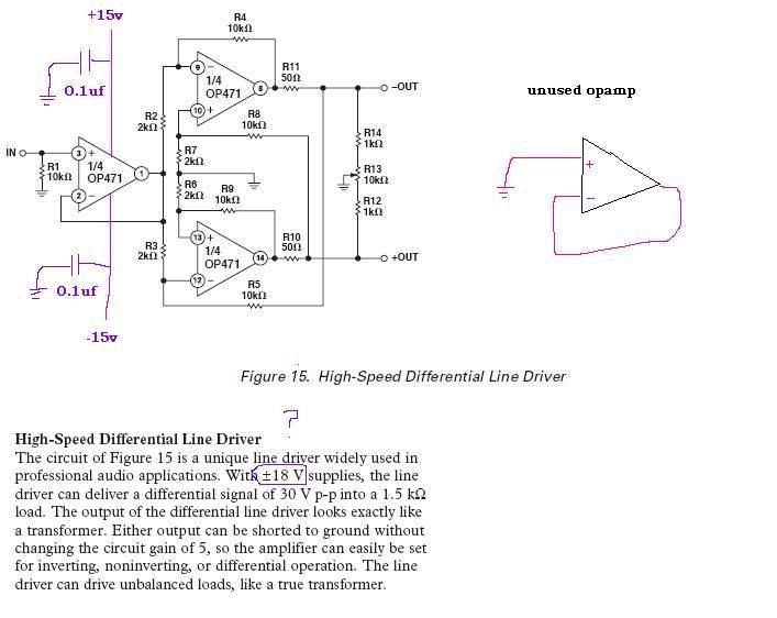
You have queried the +/-18V text; I don't know this op-amp, but +/-18V is not unheard of in some consoles; bear in mind that some 5532's are spec'ed to operate as high as +/-22V!! (Be very careful with replacement ICs if the supply is anything over +/-18V).
However........ a couple of things that could be a source of trouble:
1. There are no frequency-limiting caps accross the op-amps. Suggest 22pF in parallell with R4, R5, R8, R9. This is standard-practice when designing with this type of cross-coupled driver. Your op-amps may be going into oscillation and/or driving the outputs hard-to-rail. Have you 'scoped the circuit?
2. There are no output coupling caps. This is not really relevant to your present problem, but accidentally shoving phantom up an op-amp's output has been done more than once, and usually with unhappy results, except for the bank-balances of freelance techies :grin: . For good LF response, use a 220uF with the +ve out. Insert between the outer end of R11 and the x-coupling feedback line. Do the same for the other output.
3. The 10k balance setting pot (R13) is way too high in value, and setting the null point will be a life-time's work..... unless you have a 40-turn device!! Drop it to about 2k2. Even 5k is a hassle to set.
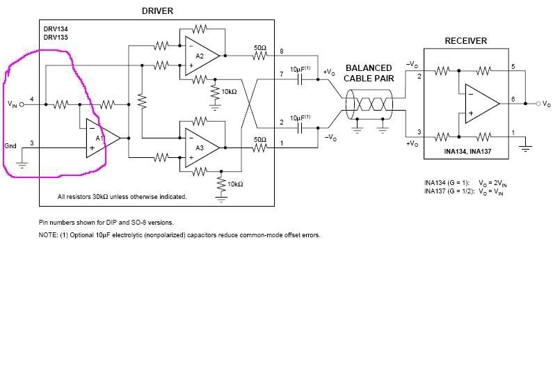
With reference to your latest question about the input configuration being different between your postings, the original post has the input buffer providing a low-Z non-inverting drive to the outer-legs of the balanced output, with the inner legs being grounded. (For what it's worth, these x-coupled outputs like a low-Z drive).
Your most recent posting has the input stage expecting an external low-Z drive to the inner legs of the balancing stage, the buffer provides a low-Z drive to the outer legs. Interesting ideato drive all input legs with low-Z.