gemini86
Well-known member
Normally I'd say you'll need a 15V transformer for the DC heaters to work, but since they're so big, you may see that they output closer to 15VAC which will work fine. I say, try it. If it doesn't work, get new ones!


Fablab said:Hello, I am realizing my G9 and I have a doubt around the power supply transformers.
Considering that the first one must be 220v:15+15v (30ma) I am not sure for the second one.
Is it better a 220v:12+12v or a 220v:15+15v?
I am sure that this is not a new question, but I have not found a reply (using the search function)
It's seems like it's highly suggested that the HT Supply be moved off board to stop any hum.
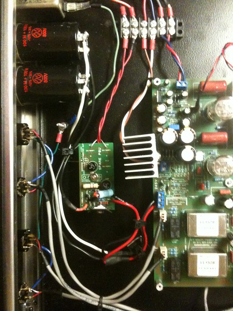
") coming from my 78s12. After some inspection it turned out be Diode D13 1N4007 as you can see in the picture.
coming from my 78s12. After some inspection it turned out be Diode D13 1N4007 as you can see in the picture.

synnys said:i connected the blue/yellow with the sleeves to the 15v input at the 78s12 location. the yellow/blue without the green sleeve is conneted to the 15v at the right side of the pcb.
synnys said:i connected the two blacks (one with sleeve other without) together (with the yellow (without sleeve) from T1 sec) at the right pin of the 15v rightside of the pcb
i connected the two greens (one with sleeve other without) together (with the blue (without sleeve) from T1 sec) at the left pin of the 15v rightside of the pcb

synnys said:btw on which pins of the xlr plug can i measure how much volt the phantom power gives me?
synnys said:no matter in which direction i turn the little trimpot on the pcb, when i select 48v (and mic and hi-z too) on the frontpaneli measure absolute 0 volt on the XLR's...
how is this possible?
0 voltEnter your email address to join:
