Universal Bargraph Driver PCB for everyone to use...

GroupDIY Audio Forum

Help Support GroupDIY Audio Forum:

This site may earn a commission from merchant affiliate links, including eBay, Amazon, and others.

SSLtech

Well-known member
Joined
Jun 3, 2004
Messages
5,447
Location
Florida (Previously UK)
Hi all,

Some time ago, I made some bargraphs to put in alll of my mic preamps etc. I made the design fairly universal, and always intended to share it with everyone, but I forgot where I saved it... :oops:

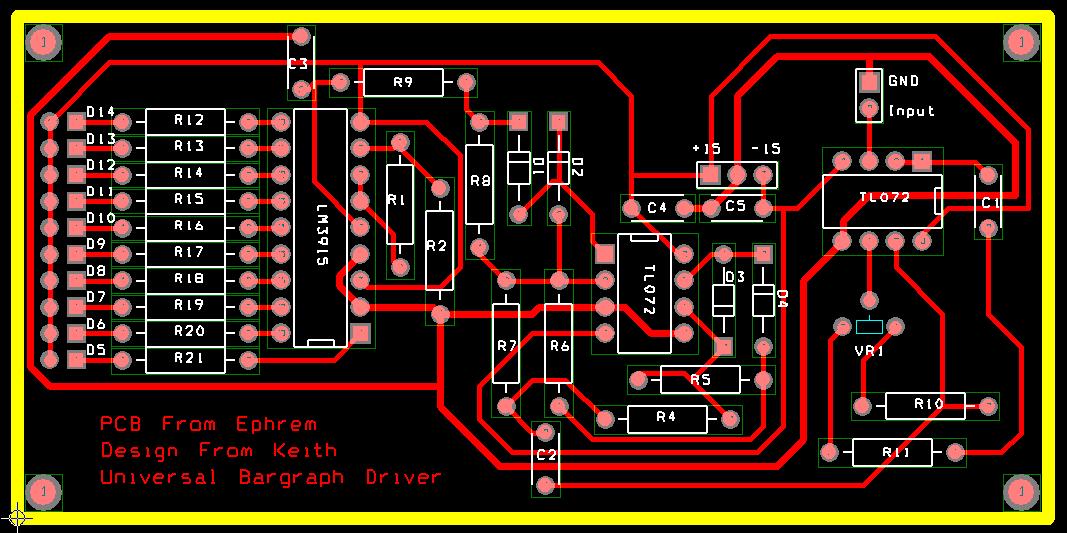
Anyway, I found it, so here -at long last- is my universal Bargraph driver PCB design!

http://www.beatbazar.com/guests/ssltech/universal-bargraph/bargraph.pdf

It's the board shown (in prototype form) in this picture:
micpre-inside.jpg


Thanks fo Kruz for hosting the information, as ever!

Keith A.
 
I apologize if this is a silly question, but would it be difficult to scale the LED's so the first 6 were 1dB each and then subsequent LED's represented a bigger range?

thanks,
Brad
 
Already done. It's in the description.

LM3914, 3915 and 3916 all have their scaling cinfigured internally. SImply select 3914, 3915 or 3916 depending on whether you want linear, log (3dB per step) or VU (1dB for the top few leds, expanding to cover 23dB total range).

Keith
 
Nice one, Keef! :thumb:

Note: if you're perfboardin' this or laying out your own PCB (for whatever reason), that "extra" half-TL072 could be used to implement a balanced input.
 
It's explained in the schematic:

2 used for precision rectifier (I need to know when things are approaching clipping, not what the average level is...)

1 used for variable gain input buffer to make this UNIVERSAL.

This will meter -10dBv signals, +4dBm signals, and can be set to whatever reference point you want or need, with no changes.

Keef
 
[quote author="SSLtech"]
2 used for precision rectifier
[/quote]

Never heard of. Sound cool though :grin:

Don't the LM39xx have rectifiers built in?
 
No. It's a single-pole device. It will work for simple, single-direction signals like the Gyraf DC gain reduction meter, but needs additional circuitry to work for 'bidirectional' AC audio.

Full information on the 3915 here:
http://www.ee.washington.edu/stores/DataSheets/linear/lm3915.pdf

Similarly, the 3914 (linear) datasheet is here:
http://www.ee.washington.edu/stores/DataSheets/linear/lm3914.pdf

The VU version (the 3916) is basically the same, but has dB spacings (from the top LED down) of 1,1,1,1,2,2,2,3dB, which translates to a scale of +3,+2,+1,0,-1,-3,-5,-7,-10 dB. You should really use a dual-pole averaging detector if you really want to approximate a 'real' VU meter, but dropping the 3916 into my PCB, you get a handy little peak-reading VU meter.

Keith
 
I was first introduced to a precision rectifier as an undergrad in an electronics class. My teacher had a build a simple audio compressor. We used a precision rectifier in that circuit. Very useful with small signals.
 
[quote author="RogerFoote"]Took, what, a year to find it? Sounds like me.[/quote]
Good lord not. Longer than that.


I did that about 2½-3 years ago. There was a version where R2 was wrongly-connected at one end (if you look closely at the prototype pic you can see that it's moved down slightly in the final, correct version.)

When I first did the document, I discovered that I'd inserted the PCB artwork, and then I couldn't find the right artwork. Bits wre on my home PC, bits on my laptop, bits at work... Then I forgot about it until I got a PM asking for the info. Then I stumbled across all the bits quite luckily, so I shoved them all into a pdf before they could get lost again!

Keef
 
Hello everyone,

Please find here gerbers files for Universal Bargraph driver SSL9k :wink: .

This is a precision full wave peak detector.
I did not find them on the forum, therefore i've created them

http://puzzlemind.free.fr/Ephrem/Gerbers.zip

pcb2.JPG


The original design is from Keith & lm3915 datasheet : http://www.beatbazar.com/guests/ssltech/universal-bargraph/bargraph.pdf

I'm not a professionnal designer. I 'm gonna test this pcb soon.
I made that circuit with veroboard. that works perfectly. Really accurate.

On this forum, I see many preamps without bargraph or peak led.

From my recording experience, You have to check preamp output level (0dB at least) before AD conversion :!:


Regards
Ephrem
 
Sorry for bumping such an old thread but i think this bargraph meter is still a nice option.
I etched Keith original design as reposted by signalflow two replys ahead.
The schematic is in that pdf too.
I'm not sure about the capacitors, if they should be ceramic or wima/film capacitors.
C4 and C5 are filtering the current and should be ceramic right?
So i could use these (sorry german site):
http://www.conrad.de/ce/de/product/531855/Holystone-Keramik-Kondensator-RDC-RDCX104K050DKA-100-nF-50-VDC-10-/SHOP_AREA_17436&promotionareaSearchDetail=005
And C1,C2 can be Wima capacitors?
Can you assume that if a capacitor connects to ground, it's normally always a filtering capacitor and should be ceramic so C3 would be ceramic too?
Would 220 nF ceramic be OK or would this Filter the wrong frequency?


Latest posts

Back
Top