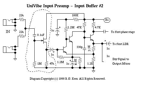
Uni-Vibe input buffer

GroupDIY Audio Forum

Help Support GroupDIY Audio Forum:

This site may earn a commission from merchant affiliate links, including eBay, Amazon, and others.

khstudio

Well-known member
Joined
Dec 27, 2005
Messages
2,116
Location
New Jersey, USA
I could use some help adding a (switchable - IN & OUT of circuit) jFET input buffer to my Uni-Vibe.

Could someone reccomend a jFET that would work & sound good for this?
(maybe j201, 2n5457, etc...? I have a few different types in my box)

Also, what is the easiest way to switch it in & out of the circuit???
Can I just jumper the original input to bypass the jFET circuit or does the whole section need to be disconnected?

Original:
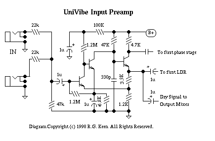
univibe1.gif


Added Buffer:
univibe8.gif


Thanks,
Kevin
 
I've read that Geofex-story a while back and was surprised why the 47k resistor wasn't simply increased to get the desired higher input-Z.

Regards,

Peter
 
I don't know enough about circuits to say... this is one reason I'm asking you guys here :wink: A uni-vibe does have a Vibe" to it in it's original form but the buffer seems easy enough... & making it switchable would be great. I've heard samples of ones with the buffer & they do have better headroom/high end... a nice option.

Kevin
 
Can imagine the added FET gives you the feeling that the original Vibe-circuit remains more intact. Just go for what works & sounds the best; while I think it won't do much different w.r.t. the simple 47k to 1M value-change, if you'd like to have the buffer then add it. You'll need to provide popless switching, so use a DPDT-switch around the dotted area and be sure to tie the lefthand side of the 1uF cap to ground with say a 1M-resistor.
To prevent pops caused by the non-zero DC-output voltage (source of the FET) you'll need to add another AC-coupling cap (say 10uF) and tie the open end (non-source) to ground as well by another 1M.

An alike story at the input-side: no added cap required, but use a 10M from the lefthand side of the 0.1uF to ground.

I'm building the NeoVibe myself now and will stick with the lower-input-impedance because I don't expect I'll ever use the NeoVibe without another box between the passive gtr-PU's & this circuit.

Regards,

Peter
 
Cool man, your building one too :green:

That board is small ain't it?

I have some LDR's that measure about right but they are the larger ones... I had to modify the board to fit both my large ones & the small ones the other guys use.

Were you going to add the components to adjust the bulb driver circuit?
That one does seem like a PLUS.


BTW, I think the F*LLtone & Analog-Man versions have the switchable or added input buffers.

Kevin
 
Are you losing signal when running multiple effects?

Maybe add a buffer to your axe so that you will not degrade, no matter how much parallel processing you have going on.
 
[quote author="khstudio"]Cool man, your building one too :green:

That board is small ain't it?

I have some LDR's that measure about right but they are the larger ones... I had to modify the board to fit both my large ones & the small ones the other guys use.

Were you going to add the components to adjust the bulb driver circuit?
That one does seem like a PLUS.


BTW, I think the F*LLtone & Analog-Man versions have the switchable or added input buffers.

Kevin[/quote]

Sure, that PCB is quite crowded ! I have one from GGG. I'm not sure yet which gizmowhistles I'll be adding. The buld driver from JC (from Canada, another JC) looks good to add yes, but apart from that I'll first be building it as is, and see from there.

Wasn't aware about those switchable buffers. I'll try not to look otherwise I might end up with a contraption that has all extensions that other incarnations have done and that was something I wanted to avoid for this build.
I got the bulb & LDRs from www.banzaieffects.com

Enjoy !

Peter
 
that was something I wanted to avoid for this build.
Me too until I did some research...

A couple links:
It seems a lot of these guys believe in the buffer (switchable)

In this guys samples you can really hear the extra headroom compared to a none buffered pedal.
http://www.lynx.bc.ca/~jc/pedalsUnivibe.html

http://www.retroman-music.com/UBERVIBE PAGE.htm

http://www.analogman.com/mojovibe.htm

http://www.haarguitars.nl/test/Merken/Specials/Mojo.htm

Parts
http://www.smallbearelec.com


Kevin
 
[quote author="khstudio"]
that was something I wanted to avoid for this build.
Me too until I did some research...[/quote]

Thanks Kevin for sharing :thumb:

I'll have a read & a listen to this new info and see how well I can resist adding new stuff. To be continued !

Bye,

Peter
 
Read it and apart from the buffer-bypass luckily there wasn't much that screamed to be added imho. The four filter-pots a bit too much I think, you might run the risk of thinking about readjusting while playing and we don't want that.

I must admit that I was disappointed with the warning about possible plops during buffer-bypass in one of the manuals.
C'mon, the time required to add the warning to the manual is more than solving the issue with a few resistors (as I described earlier in this thread) !

And 'true stereo' was used somewhere, which sounds a bit unlikely to me with only a mono input.

OK, enough grumbling for now, let's enjoy that circuit with whatever we add to it :thumb:

Bye,

Peter
 
I perfectly well realise I'm necromancing an ancient topic, but I landed here searching for information on univibe headroom issues and would like to share a recent experience on the topic.

I built a Univibe clone (http://www.geofex.com/Article_Folders/univibe/vibeupdate.pdf) and it was a tremendous success. All the way down to the tone eating and headroom issues of the very first original univibes.

1. That 47k input resistor for a guitar stomp is bordering on moronic. I'm too lazy to dig into univibe history but this is telling me it wasn't designed for guitars originally. Or maybe for some very specific active pickup configuration. No point in dwelling there, the sound sucks. Change it to 1M and it's perfect. No need for FET buffers, this resistor alone fixes everything.

2. 15VDC isn't enough to run the badly designed very low headroom preamp of univibe with any kind of modern passive pickups without clipping. By "modern" I mean designed after the year '65. It's a sound ruiner *baaaRRbp* clipping and not some cool "tone" that would be useful in any way.  Bump signal chain voltage to 20-24VDC and it's perfect. Most instructions on the net recommend 24VDC wallwarts. No point regulating this all the way down to 15V like on the neovibe schematic.

3. Since the preamp is sub-par it's also very noisy with pretty much no PSRR. Neovibe calls for TS7815 but LM317 is much better, and can be installed with very little mods and 2-3 extra parts. Also works for the 24VDC that is really needed.
 

Latest posts

Back
Top