[BUILD] 1176LN Rev D DIY

GroupDIY Audio Forum

Help Support GroupDIY Audio Forum:

This site may earn a commission from merchant affiliate links, including eBay, Amazon, and others.
I've only partly stuffed my boards. I took a quick continuity test, I have the same fault on r37 and also on another nearby resistor nearby (r36??? I don't remember the phone rang)...

You say it was this way before you populated the board... maybe there's a short to the groundplane. Can someone check a board that hasn't received any heat?

I'm going to have to wait until I the rest of my parts arrive to do any more work on this, but I suspect, if there is a trace shorted to the groundplane we might have to lift a leg on r37 and fly it out to its proper destination... I hope that's all.

Kelly
 
from the schematic it shows that one side of the R37/470K goes to the O/ Electrical ground point also the center tap of the T3 transformer. You can see it connect to the ground plane on the top of the board from a + connecting it at 4 places on the hole close to trim pot. R41,R50,C21 also do this.

I'm no expert at, but it's always a good idea to put stuff together in sections and then test if you can.
 
I've just arrived home from work to find these posts and immediately took a look at my PCB file. My deepest apologies to everyone who purchased my boards.

When I built the prototype, I found that the originally specified 2N3707 transistors never met the 250 hFE spec. Because these 'trailing edge' devices have a different pinout than newer transistors, I added a base pad to make it easier to stuff a 2N5088 (the transistor Purple uses) in the control amp. As it was a last minute decision I unfortunately neglected to notice that I had not created a space on the ground plane for the additional pads.

Since then I have purchased a batch of 2N3708 transistors and each and every one of these meets the specification needed for this part of the circuit.

I have my own board 90% stuffed but am still awaiting transformers from Purple, so I have not had a chance to test them yet. But the fix shouldn't be too difficult - if you use 2N3708 transistors or have 2N3707s that meet the 250 hFE spec, simply cut the track for the additional Base pads on the bottom side of the board. If you are going with the 2N5088 I'm afraid the fix is a little more difficult as you will have to carve around half the pad on the top side to separate it from the ground plane.

Again, my sincere apologies for this oversight. If anyone would like a refund on their purchase I would be happy to comply.

I'll post pictures of the tracks that need to be cut as soon as possible.
 
Hi Mnats, thanks for the reply.

I'm not sure I knew about the marginal spec on the 2n3707s
maybe this should be changed on the bom?

yeah, I think a little photo of the track cut would be very helpful.

glad it's something easy.

Kelly
 
I've edited this post after calming down and figuring out the obvious and easiest way to fix my prefabricated boards.

The top plated-through pads really do nothing on most of the components, save for the ones that attach to the ground plane. The error as discovered above is that an extra pad I added to the board in four places is attached to the ground plane rather than isolated from it.

1176_rev_d_pcb_base_drill.jpg

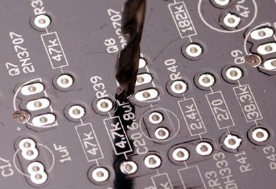
Solution: remove the top pad. Method: use a normal twist drill and gently remove the offending pads as pictured above. You can just twist the drill between your fingers. The copper pads are fairly soft and should come off after just a few turns.

You can still use this hole to mount the 2N5088 substitution after modification and, of course, the board will now work properly with a 2N3707/8 in the main footprint as well.

Archived, more complicated solutions below. See the images to identify the pads that need to be modified:

[quote author="mnats"]Here are two possible ways to solve the problem of my stupid mistake. The first one involves cutting the tracks on the back (non-silkscreen) side of the board. Do this if you are going to use the 2N3707/8 footprints.

The second solution will work for either the 2N3707/8 or the 2N5088 footprints and involves cutting around the offending pads themselves on the top (silkscreen) side. The 2N5088 uses the extra transistor Base pad that has caused all the misery ;^(


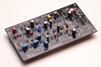
Here is the partially stuffed board. You can click on most of these pics to enlarge them.


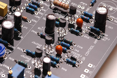
This is the section we are going to work on - the Gain Reduction Control Amplifier. Note that Q7 through Q10 have a single round pad near the oval ones. This is the Base pad that you would use if you are going to put a 2N5088 transistor or similar into the GR Control Amp. Otherwise for the 2N3707/8 you would just use the pads I have used in the example.


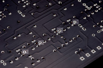
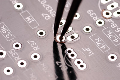
Flip the board over and cut the tracks leading to each of the base pads as highlighted in this image. You can use a small hobby knife or whatever - just make sure you only cut the tracks that go to the small round pads shown.

1176_rev_d_pcb_dividers.jpg

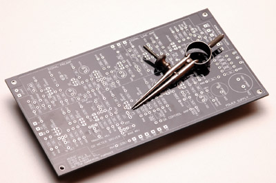
The second solution is more elegant and I think even easier to do. It is also the better solution as you get to use either transistor footprint as was originally intended. Get a pair of dividers and make sure one point is nice and sharp.

1176_rev_d_pcb_dividers_cut.jpg

Drop the duller of the two points into each round Base pad and run them in a semi-circle around the half of the pad that faces away from the transistor footprint. Do this for all four Base pads in the GR Control Amp section.

After doing either mod, test for continuity. Note that with the first mod, the  unused Base pad is still connected to Ground, but the rest of the circuit should now be separated. In the second mod, the Base pad will test open to ground.[/quote]

does this track cut fix the shorted resistor or another one?
Yes! The shorted resistor you found will be fixed as will the other three shorts.

I'm not sure I knew about the marginal spec on the 2n3707s
I can't force anyone to read my Rev D page but I would suggest reading it if you are joining in on this project. It is linked from the first post of this thread and my Rev D board sales thread. Make sure you check all the Lab threads I've linked from my page too. I'll try to add to this page as I have time to make any additions or corrections that we find along the way.

Again, many apologies for the error on the boards. If anyone feels they can't handle these mods, feel free to send your boards to me (address on the back of the packet) and I'll fix them and send them back to you. I believe that anyone who cannot do the new modification at the top of this post should probably not tackle this project anyway. All boards I send out after today will be fixed before they are sent. Thanks to strangeandbouncy for finding this problem before we all went crazy trying to find the fault.
 
Mnats,

thank you so muchh for such a comprehensive reply so quickly! about the 2n3707/8 business, what hfe should they be? are all 3708's going to work or ar we gonna find some of them are too low? Too bad |I already got my 3707's at £2 EACH . . . . .


ANdyP
 
[quote author="strangeandbouncy"]thank you so muchh for such a comprehensive reply so quickly![/quote]
I'm just glad you caught the error and that it wasn't too serious in the scheme of things.

[quote author="strangeandbouncy"]are all 3708's going to work or ar we gonna find some of them are too low? [/quote]
I don't know. It would seem from the original schematic that they were able to find some 3707s that met the spec (the range is 100 - 400 on the Central data sheet). The 3708s actually have a lower low end (45 - 650) but all the ones I bought in a batch of 25 were above 250.

Measure your 3707s before you give up hope!
 
Hi Mnats, I read your pdf's religiglessly. I wouldn't want you to think you've wasted your time. they are really very very informative.

Totally ignore me about the bom... now I see that the 3708s are even more marginally spec'd (low hfe45). No biggie here, I've learned my lessons and always order at least 5 times the required amount when buying cheap transistors... on top of this, I'm making a stereo unit so I like to try and match my hfe left to right -like q1 left unit and q1 right unit should be very close.


Hey thats a great idea using the dividers to carve out the traces.

Kelly[/list]
 
[quote author="tommypiper"]Thanks Ed, Mako and everyone. Great discussion, interesting project.

I'm looking at this. It seems fairly straight forward. (Thanks NYDave)

[quote author="JdJ"] NYD's Bridged T Schem[/quote]
[/quote]
Sorry for being daft, this attenuator is not balanced, will it still work even if it is only attenuating one of the "phases"?
Would you:
a) just run the + of the input into this attenuator along with ground, and send the - side un-attenuated into the input transformer?

b) run + and - into the attenuator and have the ground just bypass it

does the transformer following this attenuator have to be much larger than 600ohms for this to work?

Thanks for clearing my mind up,
hejsan
 
Hi Hejsan,
check the purple mc76 schematics...
there you'll see the bridged-t setup as it was implemented in many of the original 1176 revisions. I the transformer ratio is also on that schematic.

We're assuming that it will work the same now as it did then :wink:

Kelly
 
Hi - I've posted an easier and better solution to the problem with the boards:
http://www.groupdiy.com/index.php?topic=246397#246397

Should be simple enough for any DIYer :wink:
 
Thanks, Mako. :thumb: Looks like piece of cake.

I think many of us are now waiting for the output iron group buy to be offered. Anything exptected soon? A timetable? No worries... Just wondering when it might be projected to happen, if anyone knows.
 
Tommypiper- it was a piece of cake.
I just did a little work on this last night...
so close to completion... so.... close...
Unfortunately my 2n3707s all tested with hfe around 140-150
The 5088's with a spec'd hfe of 300 to 900 will work regardless.
gotta wait for those.
and then there's those transformers.
Edanderson? are you listening. can we bother you for a quick status update?

Kelly
 
mine is so nearly done! My2n3707's were ok. Just one thing, apart from output iron, that is,


Mnats says that the 30v rail is rated at 50ma, the10v rail must be loads less than that, or why use a zener? so why does the bill of parts at gyraf.dk suggest a 25-0-25 rated at 500mA? surly this is more than 10 times too large? I believe in headroom, but thats outrageous! 25VA for, by my reckoning, 2W!!!!!!

Before anyone shouts at me for having missed the obvious(As Usual!) I have spent at least 3 hours trolloing through all the 1176 stuff.

CAn anyone expain, or suggest a suitable rating?


Many thanks guys

ANdyP
 
re: power transformer - in order to get both +30V and -10V DC rails you need at least a 2 x 25VAC transformer; dual 30VAC secondaries would be safer. look at your actual line voltages where the unit will be installed and leave yourself a margin for day to day dips.

as for the VA rating, while the circuit itself may draw only 50ma, you have to throw some power away for regulation to get that clean 50ma. and when a 25VA toroid is only slightly more expensive than a 7VA toroid, why not oversize? the less load you put on the power transformer, the smaller the stray field it will generate, reducing interference headaches. the transformer will also run cooler and last longer. the larger transformers are more efficient and less likely to have the output voltage droop under load.


i hope to have some output transformers to sell by the end of the month. i will post an ad in the black market when they are ready; please do not contact me before then.

ed
 
Thanks for the update Ed. Please post in this topic when you get the black market up. I'd hate to miss out. :cry:
Cheers and thanks alot for doing the order.
Kelly
 

Latest posts

Back
Top