[BUILD] 1176LN Rev D DIY

GroupDIY Audio Forum

Help Support GroupDIY Audio Forum:

This site may earn a commission from merchant affiliate links, including eBay, Amazon, and others.
[quote author="pH"]Quick question about using the input transformer board with the Altran: if I'm reading the board correctly I need to link B to C, and E to F, yes?[/quote]
revd_trx_brd.gif

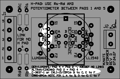
Yes, that's what I put at the bottom of the board.
[quote author="pH"]This would link pins 2 and 3 to the ground plane of the little board. [/quote]
How do you figure? Note that where it says "Altran C-3837-1" there is an arrow indicating where pin 1 goes. That means pins 6 and 7 will be connected to the ground plane.

On the Altran, pin 6 goes to the can. On the Cinemag CMLI-15/15PCA (a 1:1 transformer not explicitly shown, but that shares the same footprint and pin 1 assignment) pin 6 goes to a shield and pin 7 goes to the can. It wasn't easy trying to fit all the information at the bottom of the board, so even though it says to connect the two links, only one is going to the can with the Altran.

[quote author="pH"]Can't find a pinout for the C-3837-1 so I'm wondering what's happening here.[/quote]
C-3837-1.gif

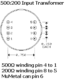
I've now linked to it from my Rev D page. Here it is courtesy of Ed.
 
Well here is a cautionary tale...

I finally got all my pieces together for my REV D V2 1176, which I've been building over 3-4 months as time/money has allowed and I was ready for the final hook-up.

I printed the schematic so had it on record along with the original schematic for the UREI Rev D and thought I was prepared for things... but...

I noticed having soldered the screw terminals on the PCB it covered up the colour coding for the output transformer... no problem! I'll just print it out as it is laid out in MNATS beautiful document, so I do and wire up accordingly...

The big moment arrives, I flip the switch BRIGHT lights and flames as R32 goes up in smoke... hmm funny, I had checked my wiring all looked good, voltages were good, what went wrong?

So I desolder it and then work backwards... but wait R32 was going to the wrong winding.... something is fishy... I open up the MNATS REV 2 document and the output transformer colours DON'T match the board... penny drops!!!!

I had BOTH the REV1 and REV2 manuals of MNATS and while I was working from the correct schematic for REV2 and the UREI one (which is great since it shows that you have to join the CT Orange and Yellow wires together if you have Ed's transformer) but the OVERLAY was REV1 which DOESN'T match up with REV2 (Mako you may want to add this to your list of changes to your REV D site in case anyone else makes the same blundering mistake!).

So a quick resistor change and re wire of the output transformer and she is alive and well!!! She passes audio, clean as a whistle, all control work just got to get to the calibration steps.

My Meter in GR is deflecting all the way to the right, I assume I need to “0” it and hope that adjusting the “0” trim will sort that out. GR is moving downscale when audio passes and the Bypass and OUTPUT Meter selections are working, so all seems good here.

I just have a question about matching Q1 and Q11. Can one do this in circuit? I have installed DIL sockets so I can swap them out, but want to know if I can use say use just Q1's socket and surrounding circuit and just plug in various 2N5457's? Where would be the best place to measure and can anyone explain this procedure?

I know Mako has a 3rd Video installment he will hopefully be doing and not sure if this covers the matching process but it may be useful to know.

Thanks in advance and thanks to Mako for an AWESOME project!!!

Cheers

Matt
 
And we are back... Hah hah

Ok,

So This morning a I set the "0" meter trimmer to zero and went through Mako's Calibration videos and set the 'Q Bias' and 'Null Adjust' trimmers as per his EXCELLENT videos!

So the last adjustment I need to make is to the "Tracking" trimmer.

As I shared I just put in 2 x 2N5457's in Q1 and Q11 as a starting point but they are not matched, but from what I gather they will have had no effect on the 2 set-up procedures I've done because in the 'Q Bias' set-up you short point 22 to Ground, effectively taking the GR circuit out of action.And in setting the 'Null Adjust' trimmer you take R44, the 'Tracking' trimmer out of circuit using a shorting plug.

Since there isn't a 3rd video yet I just want to know as per my above question, can one 'match' the 2 FET's in circuit? And then I'll have to refer to the UREI manual for the final set-up.

Thanks in advance!

Cheers

Matt
 
[quote author="bluezplaya"]I am trying to find where "x" and "y" on the meter switch board wire to on the main board.[/quote]

They don't, they connect to the output XLR. "X" goes to Pin2, "Y" goes to Pin3.

Cheers

Matt
 
Matt, I am working on my unit right now and I noticed your thread about wiring the output transformer. I am using the Cinemag CM-96731. Where exactly is the color coding wrong? I certainly don't want to screw anything up when i turn it on.

Adam
 
Which REV board do you have?

Mako's overlays are correct, it just depends on which board you have.

The transformer colour code are as follows, both from the EDGE (near C14) of the PCB TOWARDS the AC input.

REV1: Brown | Violet | Whit/Black | Whit/Red | Black | Grey
REV 2: Brown | Whit/Black | Whit/Red | Black | Grey | Violet

You can tell the difference by noting the changes that happened between Board REV's which are on Mako's site, but for the record they are:

Rev D Version 2 changes:

* Fixed ground plane shorts on Q7 - Q10
* Added alternate pads for Q5, Q12, and Q13 so 2N5088s can be used in these positions too (like the Purple MC76) You can still use 2N5088 transistors for Q7 through Q10
* Made C2 and C11 0.2" pitch rather than 0.1"
* C18 Pitch narrower for better fit
* More room for Q6 + heat sink
* Ground pad near Pad 7 to aid proper wiring
* All pads for external wiring changed to 50 mil holes
* AC IN pads larger
* Place for shorting pins for R44 to assist calibration and room for three pin header to hold shorting plug - refer to PDF overlay
* Correct value of resistor R12
* Power supply has its own ground plane
* Final stage of line amp has its own ground path

The shorting pin near R44 will be the dead giveaway if you have a REV2 board or not.

Cheers

Matt
 
I have a Rev 2. It is confirmed then. I wired up correctly. While you're available online, I also would like to confirm the input transformer. I am using the Cinemag CMLI-15/15PCA and have it mounted to the board correctly. I have jumpered pins B and C, as well as E and F. I also jumpered the 2 links for "no H Pad". What is H Pad? Is that for wiring a 600 ohm attenuator? I will be using a 1k pot for now, until I can get my hands on an attenuator.

Also, J2 is not marked for any -/+ so I assume it shouldn't matter. I will wire J2 to the input connectors on the board. But where I'm slightly confused is where to wire the input pot...between pins 1 and 5? So that means 2, 3, and 4. But which is wiper, etc?

Thanks in advance,
Adam
 
[quote author="bluezplaya"]I have a Rev 2. It is confirmed then. I wired up correctly. While you're available online, I also would like to confirm the input transformer. I am using the Cinemag CMLI-15/15PCA and have it mounted to the board correctly. I have jumpered pins B and C, as well as E and F. I also jumpered the 2 links for "no H Pad". What is H Pad? Is that for wiring a 600 ohm attenuator? I will be using a 1k pot for now, until I can get my hands on an attenuator.

Also, J2 is not marked for any -/+ so I assume it shouldn't matter. I will wire J2 to the input connectors on the board. But where I'm slightly confused is where to wire the input pot...between pins 1 and 5? So that means 2, 3, and 4. But which is wiper, etc?

Thanks in advance,
Adam[/quote]

Adam,

To the best of my knowledge the 'H Pad' is if you ARE using a pot since a 1K pot will not give you the desired taper than the circuit needs.... you will need to do some more research on this. You jumper the PAD IF you are using an attenuator.

Likewise you will need to see what others have done using a pot configuration, I believe it was spoken about earlier in this thread somewhere.

J2 is marked if you look at the PCB, note how one hole is Square, this indicate +, the round hole is -, it isn't on the overlay but look at the solder pads.

Cheers

Matt
 
[quote author="bluezplaya"]Okay, I found the positive hole on the main board but don't know where the positive side is on the IP tranny board.[/quote]

Glad you found that :thumb:

On the main PCB is should be on the right side off the edge of the PCB. I think it is only natural that the PIN 2 and PIN 4 on the input side would like up on the output on the input transformer PCB, so the hole closest to Pin 2 if you look at the PCB horizontally is + and Pin 4 is -. I hope that helps.

Also going to use this as a BUMP for my own questions RE FET matching for the GR section, any help would be appreciated.

Any other REV D builders around?

Cheers

Matt
 
Will the Nessai Meter listed on JLM audio's website work for the 1176 Rev D? It says its a Sifam AL29WF look-alike. I've been trying to find an affordable Sifam, but no luck so far. I'm assuming the buffer circuit must be included, no?

http://www.jlmaudio.com/VU%20Buffer.htm
 
Also going to use this as a BUMP for my own questions RE FET matching for the GR section, any help would be appreciated.

Hey Matt, I used the little testrig as found in PRR's Post (in the middle of the page, 05. Jan 2005, 6:17). It's not an 'in-circuit' method, but worked perfectly on my two revision J stereo clones.

hth,
christoph
 
Hi Christoph,

Thanks very much, it was most useful and I not have a matched pair of FET's, wrote down all the measurements of the others incase I need to find similar/same one later (though out of 20 I got one pair).

Cheers

Matt

[quote author="crisotop"]
Also going to use this as a BUMP for my own questions RE FET matching for the GR section, any help would be appreciated.

Hey Matt, I used the little testrig as found in PRR's Post (in the middle of the page, 05. Jan 2005, 6:17). It's not an 'in-circuit' method, but worked perfectly on my two revision J stereo clones.

hth,
christoph[/quote]
 

Latest posts

Back
Top