carnitas
Member
luis, FWIW, i burned R32 twice and after i got my wiring figured out everything works fine. The first time I burned R32 i didn't realize what i had done and left the unit on for a minute before i figured it out.


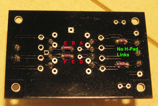
Do a high res photo of different angles of your build and post it up. Maybe someone visually can pick up what's wrong with it. Close up photos of sections like pots wiring, meter wiring, pcb board close up, xformer close up, etc. get good lighting when taking the photos so it comes out clear. Also take a pic of the underneath in all angles.luis said:Thanks for the response, but something must been damaged beside R32.
I also replaced all transistors, but no sound, no meter and everything is microphonic: Do you know that technique to check tubes in guitars amps, by tapping them with a pencil? If I tapp anywhere in the case, board, tranformer I can here the sound!
I don´t know what more to do. The psu voltages are fine.
Are the reference voltages for the rev D the same for the others versions? Should I check them?
Thank you
If you have the push button PCB boards from Hairball, it uses the little connectors instead which is far better.Dean Roddey said:I ordered the matrix pins from the BOM. I just got to the point of being ready to put them in and noticed that they are crimp on pins on the male side, not the sort with tails to go through a PCB board. I looked and the picture for the P/N indicated in the BOM would indicate that they are through board tails, but that's not what I got. Anyone else have this problem?
If it's just an error on Mouser's part, I'll just order some more. But I don't want to pay 2 day shipping just to get the same wrong stuff again. But if I don't get them in this week, it'll be yet another week before I get this thing put together.
OIC, Well I got the soldered version on my male matrix for my BOM list, though it does not look like the bottom pic I have attched. It looks like the connector pin versions. I actually prefer the one in the bottom pic for matrix pins.Dean Roddey said:I'm doing the rotary version, and both sets of pins are crimp on types in my case.
You can pick them up at your local electronics store. They are called in Australia as PCB Pins and PCB sockets for easy termination. I have always been told that hard wire is better anyways.Dean Roddey said:Then it looks like Mouser sent me the wrong ones then. Oh well. Screw it, I'm probably just going to hard wire it. Live fast, die young and all that. It'll probably be more robust in the end anyway.
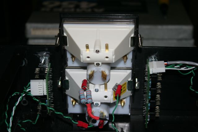
Dean Roddey said:For the ground wire that's on the side wall of the output transformer, should that just be grounded to the screw holding the transformer to the case or just ignored because the grounding is being handled by the star ground at the input XLR already?
Dean Roddey said:And the xformer would seem to have an extra pair of wires (yellow and orange), The are just to be ignored?
Dean Roddey said:Blue and red go off to the XLR, and the other 6 are paired up in sets one from each side of the transformer, as per the wiring diagram.
canidoit said:What tools did you use to cut those out perfectly.
Echo North said:Dean Roddey said:And the xformer would seem to have an extra pair of wires (yellow and orange), The are just to be ignored?
They get connected directly together.
Dean Roddey said:Blue and red go off to the XLR, and the other 6 are paired up in sets one from each side of the transformer, as per the wiring diagram.
Yes.
Enter your email address to join: