[BUILD] 1176LN Rev D DIY

GroupDIY Audio Forum

Help Support GroupDIY Audio Forum:

This site may earn a commission from merchant affiliate links, including eBay, Amazon, and others.
luis said:
Hi,

I noticed an intermittent noise in my compressor that only goes away when the input attenuator is completely turned off, or when I disconnect the input transformer from the main PCB. So. While trying to figure the problem (checking for shorts,etc) I noticed that the + and -  pads in the input transformer PCB have continuity. Can someone tell-me if this is normal  ????

Thanks

Problem solved:
I had a short in my input cable! Funny how these rare things only happen when we are not expecting!
The Unit is compressing and sounding excellent.

Thank you all.
Calibrating... ;D
 
Hi D builders

I'm having a problem with hooking up my 12v Hairball VU lamp...

OK I understand I can tap into the juice off the AC PT secondary which is roughly 28.4VAC.
I need to use about 220ohms to drop this to 12ish VAC right??

I found a couple 470ohm resistors so wired them in parallel & that gives me a reading of 230 ohms.
So here's where I'm confused...
I attach the pair in parallel to one leg of the PT secondary (at the board) & measure
from the PT center tap to the resistors & I still get 28.4VAC Shouldn't I see a drop in voltage??

Cheers
Sean
 
Ringwraith said:
So here's where I'm confused...
I attach the pair in parallel to one leg of the PT secondary (at the board) & measure
from the PT center tap to the resistors & I still get 28.4VAC Shouldn't I see a drop in voltage??

Is the load (lamp) attached?
 
No, I wanted to make sure I had a proper voltage before frying the lamp. Is this my problem?  :-[

Cheers
Sean

OK I took a leap of faith... lol
Lights up good & the voltage is 9.6 between the light lugs.
I'm using 1W Metal Oxide resistors in parallel. If I remember
correctly, this doubles the wattage so is 2W enough for this drop?
The resistors are getting a bit toasty.

Thanks
Sean
 
I'm having problems with the discrete meter circuit callibration: When I turn the trimmer Full CW or Full CCW, the meter does not move.
Checked solder, cables, and everything seems OK.

Did a search on the forum and found that some members had problems with this step, but none of them with a problem similar to mine.

Can someone help?

Thank you all
 
IT LIVES!!!

Hey just wanted to put out a huge THANK YOU to the prodigy forum.  I have been wanting to get into electronics more and this was my first real DIY project.  I have done some paint by numbers stuff, like the SCA pres (which sound great BTW) but I really wanted to actually learn a little more about what I was doing.  I still have a long way to go but the 1176 fired up first thing.  I was a little concerned because it wasn't compressing immediately but the Q bias was waaaaaay off.  So after a very quick adjustment, its compressing and sounds great. 

I will properly calibrate it tomorrow and keep my fingers crossed that nothing burns up, but so far so good.
 
Hi guys

I would like to make a rev D with Homnite Little Demon
any of you has already done?
can bring benefits to the sound?

Thanks :)
 
hey fungo!

guys,in never thought about it.
i used metal film resistors, panasonic and wima caps, like a lot of people around here.
does vintage models caps and carbon comp resistors give a more pleasant sound?
is that so much different?
in the simplest term, does a 1176 with metal film res and modern caps sound anything like the original?
 
Hey Canidoit, thanks for all the tips on my build BTW.

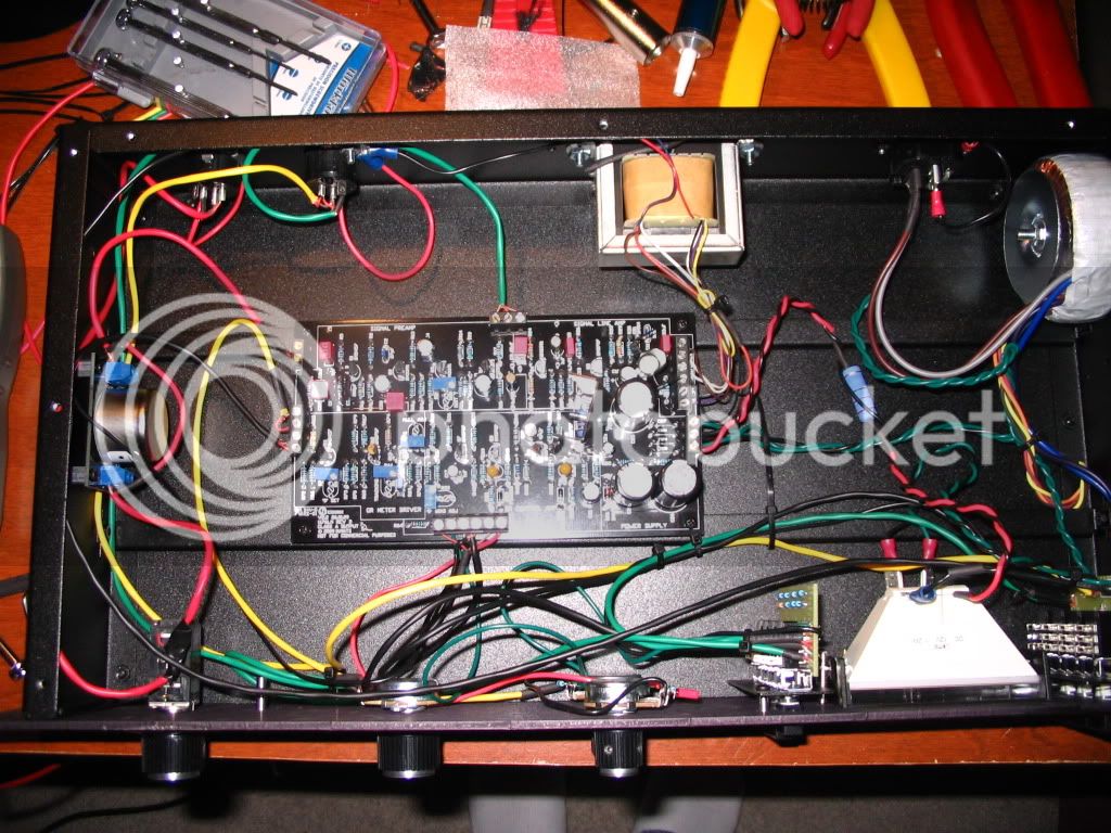
I thought I would include at least one pic of the insides.  Nothing extraordinary here; pretty standard parts based on some of the BOM's floating around and the basic parts from hairball.  I bought enough components and boards for two but I think I may populate my second board with all carbon and old school components instead to see if there is any audible difference. 

IMG_0343.jpg


I cleaned up the wiring a bit more before I buttoned her up, set the resistor for the VU lamp apart from the wire with it and a few small things.  Being my first major project the wiring is pretty messy but to my surprise it is totally quiet with no hum or any noticeable noise.  I didn't even scrape the paint back for the grounds.  I used Mogami balanced console cable for all the balanced connections, as I had a bunch left over from wiring my patchbays.  I love that stuff because it is so small but still really quiet.

Anyway thanks again for this forum!  (Oh and if anyone sees anything wrong with the insides, feel free to let me know!)
 
T-rex said:
Hey Canidoit, thanks for all the tips on my build BTW.

I thought I would include at least one pic of the insides.  Nothing extraordinary here; pretty standard parts based on some of the BOM's floating around and the basic parts from hairball.  I bought enough components and boards for two but I think I may populate my second board with all carbon and old school components instead to see if there is any audible difference.  

IMG_0343.jpg


I cleaned up the wiring a bit more before I buttoned her up, set the resistor for the VU lamp apart from the wire with it and a few small things.  Being my first major project the wiring is pretty messy but to my surprise it is totally quiet with no hum or any noticeable noise.  I didn't even scrape the paint back for the grounds.  I used Mogami balanced console cable for all the balanced connections, as I had a bunch left over from wiring my patchbays.  I love that stuff because it is so small but still really quiet.

Anyway thanks again for this forum!  (Oh and if anyone sees anything wrong with the insides, feel free to let me know!)
Those Hairball cases look pretty slick. Well done mate  :). If you are going to go old school on your next build, also get the UTC transformers for it I reckon.

Be careful with that fat chunky resistor for the VU lamp. That gets very very hot! I am not sure how far apart that black cable is from the fat resistor but after a while, like years maybe, that black cable near it might start feeling the effect of the heat and also the paint below maybe?? Better to make a nice separation now than later on, which is a pain in the ass once you have racked the whole unit.

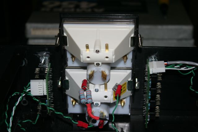
Hairball and others do this 2 little resistor in parallel version which they hang off the VU meter.
vu.jpg

 
Thanks, yes I untwisted that and set the resistor a couple of inches from everything, the case and the other wire, with some plastic ties. 

yes the Hairball case is amazingly easy to use.  Really really nice and simple to work with.  I definitely wanted a case as my metal working skills and bad to say the least.
 
Awesome!

Nice to see the case used is a finished build so quickly.  :)

I used two resistors in parallel because I didn't have an appropriately valued (R and W) single resistor.

Thanks,

Mike 
 
Yeah, I had the board stuffed and all the parts waiting, as soon as I got the case I just put it together and wired up all the off board connections.

I know there is another thread for the cases, but I have to say their great.  The standoffs make everything very easy to put together and shaved a ton of time off the assembly.   
 
Has anyone used a Jensen JT-11 input transformer in their Rev D? I'm considering building on using it and the UA-5002 T2 output transformer, if possible.
 
Hi guys.
Looking to build 1 of those i have almost everything now.
one question to start with...I have a 600:600 Jensen transformer.
I was wondering if this could work in the Rev D?

Thanks.
 
luis said:
I'm having problems with the discrete meter circuit callibration: When I turn the trimmer Full CW or Full CCW, the meter does not move.
Checked solder, cables, and everything seems OK.

Did a search on the forum and found that some members had problems with this step, but none of them with a problem similar to mine.

Can someone help?

Thank you all

Well discrete meter calibration is done, but there is no way to do the tracking adjustment step:

Turning or removing the R44 out the circuit does not change the meter needle position. Checked solder, checked the trimmer, changed some transistors (q7-q10) like suggested by someone in the forum… no solution!
The 2n5457´s FETS are hfe matched by a cheap multimeter, so maybe this is the cause of the problem. Is there any hint or clue of what might be?

Regarding the audio and compression, everything seems working just fine, I just have a small HUM that I almost 100% certain that is caused by the toroid that will be replaced, and I also noted that if the input cable is connected, even if there is no signal if I put the Attenuator past half way, and the Output at Max there is some noise (the converters should be clipping). If the input cable is disconnected this doesn´t happen. His this the normal behavior?
Thank you all,
Luís
 
hello
Can you tell me if the orange drop instead of wima may give some advantage to the  REV D sound?
I want make a old style rev D with carbon composition resistor and orange drop caps...
thanks
 
I'm  wiring up a 1176D V2 with Hairballs Pushbutton instructions, & am wondering why the one of the molex ratio PCB connection out wires  is supposed to be wired to the attack pot when the attack pot is also wired to the main PCB board 19 on pictures of builds & diagrams, can someone clarify the attack pot wiring from the ratio PCB? I'm using the meter pcb pushbuttons for disabling the attack switch.

I've spent ages trying to work this out with schematics & diagrams / pictures but am much too brainless to work out what is supposed to be exactly happening?  ???

Thanks JK
 
trancedental said:
I'm  wiring up a 1176D V2 with Hairballs Pushbutton instructions, & am wondering why the one of the molex ratio PCB connection out wires  is supposed to be wired to the attack pot when the attack pot is also wired to the main PCB board 19 on pictures of builds & diagrams, can someone clarify the attack pot wiring from the ratio PCB? I'm using the meter pcb pushbuttons for disabling the attack switch.

I've spent ages trying to work this out with schematics & diagrams / pictures but am much too brainless to work out what is supposed to be exactly happening?  ???

Thanks JK

I have a new guide that explains it better.

http://hairballaudio.com/docs/FET_Compressor_PCB_Board_Info_V2.pdf

The GRN connects to the bypass switch.  When pad 22 is connected to GRN on the ratio board you are compressing.  On the earlier documentation I indicated "Attack Pot" because I have always put the GR bypass on the attack pot.  Wrong on my part.

Check out the new doc.

Thanks,

Mike
 

Latest posts

Back
Top