dedicated, overdesigned B+ psu

GroupDIY Audio Forum

Help Support GroupDIY Audio Forum:

This site may earn a commission from merchant affiliate links, including eBay, Amazon, and others.

enthalpystudios

Well-known member
Joined
Sep 15, 2005
Messages
539
Location
kent, oh
Anyone have a link I could start with for large supplies? I'd like to try for a power supply that I could use for many tube projects, 300vdc.

My first concern, however, could a low ripple psu like this be built without knowing the exact current draw? Also, could performance (ripple mostly) be affecting by drawing less current than the psu is designed for?

If not, than I'd like to shoot for an overbuilt psu with plenty of headroom, so that I could power different projects from the same unit. Otherwise, I'd better figure out exactly what I want to power so that I can have a specific load in mind.

Also, is this a poor idea from the standpoint of distribution, that is, will it be unsafe to carry high voltage dc across available connectors, perhaps xlr or some other common locking connector?

It just seems like a waste when you think about building projects that each have a their own power supply, especially when your plans often involve similar voltages. Would help noise as well.

I guess it's kind of the lunchbox strategy, but for tube gear.
 
Real quick addendum, perhaps someone has a schematic for a the B+ psu's Universal sold to be used with 610 and 1016 modules

quote from the 67 UA catalog:

400-350 Power Supply delivers up to 350 milliamperes of direct current at 300 volts, continuous duty. Three section filter. A positive 70-volt tap is provided so that filaments may be positive biased with respect to B-.


This sounds about right for me, and although it sounds nice to have a simple way to float the heater reference, I'm not sure if that's totally necessary for my needs. Single rail should be fine.

thanks for any comments anyone has.

billy
 
oh cool, mouser has hammond toroids like 182L117, 234VCT at .95A, and larger, prices arent the worst really. Thats a lot of B+ current I would think, not knowing all that much, won't most things a diy'er like me would make, preamps, line amps, compressors possibly, be around 5-10ma per plate at the most?

I guess I need to find some huge freaking diodes to build a bridge and pot it thermally in a large heat sinked can.

If anyone has it, as I don't have a scanner, but on page 162 of "building valve amplifiers" there is a schem and a contruction photo of a bridge rectifier utilising 12 caps and 12 diodes, each cap in parallel with each diode, 3 sets per side of the bridge.

Is this just super overkill bridge rectification? Will it pull too much extra current, or will using it with a very large electrolytic filter cap pull large inrush current? (too large, possibly)

I've been wondering about that style of rectifier for a while now.
 
the diodes wouldnt be the problem i think.
as long as they can stand the inverse voltage.
with a B+ of 300v even a simple 1n4007 will do
maximum current is 1A!
so maybe it is little risky so use 2A diodes or more
or even use a simple bridge of 35A 1000v those things are really cheap and thats really overkill
they cost like 2.5€ or something
 
altough i would go for 1000v bridge. doesn't cost more and you're really safe.
but indeed 2€ and you have a bridge.

the caps thats gonna be another thing.
altough at those voltages i suggest to use a not to great cap at the input (100µF or maybe 220µF) just after the bridge that is.
after that use a good L of like 10H. i have a 7H l that can do 1A its gonna be a big one ;).
after that you can add like enough capacitance. i think 2200µF total will do.
 
[quote author="enthalpystudios"]Anyone have a link I could start with for large supplies? I'd like to try for a power supply that I could use for many tube projects, 300vdc. [/quote]

The little Gamp supply boards I designed should do that, particularly if you use them with an LC filter or two.

My first concern, however, could a low ripple psu like this be built without knowing the exact current draw? Also, could performance (ripple mostly) be affecting by drawing less current than the psu is designed for?

Yes; use them with less current draw than the design load, and you'll get less ripple than you planned on. All to the good, I'd say.

Also, is this a poor idea from the standpoint of distribution, that is, will it be unsafe to carry high voltage dc across available connectors, perhaps xlr or some other common locking connector?

I'd be a little nervous about XLRs; I've successfully used octal plugs and sockets, and I'd guess Jones plugs and sockets would be fine too.

It just seems like a waste when you think about building projects that each have a their own power supply, especially when your plans often involve similar voltages. Would help noise as well.

I guess it's kind of the lunchbox strategy, but for tube gear.

I think it's doable; probably the biggest hassle would be finding a good grounding scheme.

Peace,
Paul
 
Here is an adjustable and regulated PSU. It has B+ and neg. voltage for fixed bias stages. I'm going to build it for a bench supply.


here's the schematic. J1 is where the xfmr secondary goes. Pin 1 & 3 = AC, Pin 2 = center tap

here's the component placement

here's the bottom copper. (this is mirrored already, so it's ready to go if you want to etch your own board. just make sure when it is printed it is 4x4.9 inches)

If you don't need the neg. bias voltage then you can omit C4, D8, D9, R2, and RV2.
 
Sorry, I should have included that info the first time. The sec. V should be at least 300-0-300v(600v w/a center tap). The xfmr current should be at least 250ma.

The power supply itself should do 250ma but I am using a 200ma fuse on the output.

Edcor has a pice that is 300-0-300v@250ma w/a 6.3v@4A heater for about $60. But I'm getting them to wind me one that has 400ma of current on the B+ sec to give myself a little headroom.

Also the power mosfet should have a large heatsink on it. I got a 3x4in finned aluminium one from an old computer monitor that died on me.
 
wow thanks gentlemen! i do have those boards from you still paul... i was going to use them to build a couple champ amps, but i decided to go with 5y3 rectified, tweed/choke style circuits, and figured the boards you made would be better somewhere else.

and what is this talk of pi filtering i read during my googling about? i can't seem to google up a definitive answer... is PI an acronym?
 
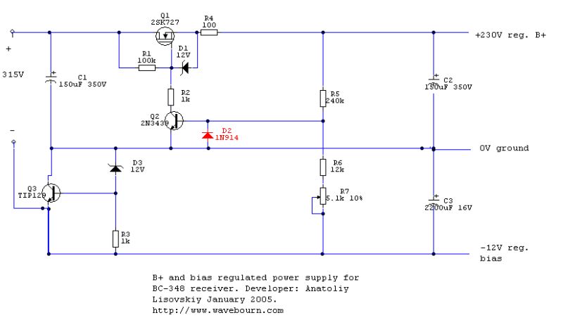
You may use this one:

bc348bplus.jpg


A first, it starts softly, raising a voltage up slowly, waiting for tubes to warm up and to start consuming a current. As the result of a current, due to a positive feedback it more quickly increases output voltage up to a regulated value, after that a positive feedback stops working, but a negative feedback starts to dominate, stabilizing output voltage on a given level, and decreasing a ripple level, without a costly and heavy chokes, without vacuum tubes to regulate output voltage.

Please be advised that no one polarity of a rectifier and filter cap must be grounded!
Also, it produces a negative bias voltage that may be used for good, otherwise leave it as is (it is a positive feedback loop for soft starting).

Vout=12V*(R5/(R6+R7)) so you may vary output voltage.
Minimum input voltage should be no less than 5V + ripple + Vout + 12V.

However, you may use it for another voltages. For example, 36V zener may be used for a bias stabilizer (it is a shunt regulator that takes the current from the entire amp), and resistors in feedback recalculated for 350V output (however, make sure that selected transistors and electrolytics can work on such voltages), to power 6L6 amp. 400V rectified in such case would be enough.

__________________
Anatoliy Lisovskiy
Audio Art Engineer
Walnut Creek, CA, U.S.A.
[email protected]
http://Wavebourn.com
 

Latest posts

Back
Top