Need HELP Reading - SMT Resistor Values, codes ***

GroupDIY Audio Forum

Help Support GroupDIY Audio Forum:

This site may earn a commission from merchant affiliate links, including eBay, Amazon, and others.

khstudio

Well-known member
Joined
Dec 27, 2005
Messages
2,116
Location
New Jersey, USA
I'm reverse engineering an EQ3d & have 90% of the parts figured out but -
I NEED HELP!

How do you read SMT Resistors :?:

How do the codes work :?:

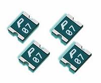
Some of them have what appears to be an 8... but the two circles aren't connected... like a % sign with NO slash & the circles straight up/down???

EQ3d - PICTURES & FILES LINK:

http://www.twin-x.com/groupdiy/thumbnails.php?album=72

I got this responce but it didn't answer the above question:
Quote:
It uses SMT resistors with very small numbers.... I've never had to figure them out before, HOW


SMT resistors are coded similar to color bands on a thru-hole resistor.

4 digits usually=1%
3 digits usually=5%

Example:
102=1K 5%
1001=1K 1%

Anything under 0603"(.060"X.030") will not be labeled. Usually 0603 and larger jumpers are labeled 000

Quote:
Also, some of them are just plain "white" are they just "zero ohm jumpers?


SMT ceramic caps are almost always not labeled. You would have to remove the cap and measure with a LCR meter to know for sure. Same for 0402 and smaller resistors.

Tant caps are sized "A case" "B case" etc. but usually have the same type code, or they have the actual value printed.


Vetsen


Thanks,
Kevin
 
There's also 2 (regular looking) green resistors with (Brown, Black, Brown - GOLD)... 3 bands & Green... never seen that, any idea's :?:
Their connected to the XLR out.


Thanks,
Kevin
 
[quote author="khstudio"]I NEED HELP!

How the hell do you read SMT Resistors :mad: :?: :?: :?:
[/quote]
How about this ?
017B5057.jpg
 
[quote author="khstudio"]Wow your smart...[/quote]
I'm not, I was just feeling a bit corny after my lunchbreak, sorry :wink:

If your so smart then maybe you can help :green:
(I guess I asked for that one, huh?)

K
Hmm, in addition to the link from Jakob I wouldn't know much more myself.
Can you lift one pin or trace of unknown resistors & measure ?
 
I wish... surface mount components... tiny.

I may have no choice.


Jakob THANKS :thumb:
I never knew that! They're marked L1 & L2 instead of R? like the resistors... that explains that one.


Kevin
 
It may not be a resistor. Can you take a pic of the component? I would be able to help you out a lot better that way.

It's not a good idea to try to lift one pad with SMT stuff. Most resistors and caps are ceramic and fracture with little effort. I deal with this stuff everyday at work. There are times ceramic res break just by stress and flexing of the PCB.

If you decide to remove it, you will need smt tweezers or two fine soldering irons. Oh, and two really steady hands.

You could reflow both joints at the same time and tilt only one side up keeping the other-side in the molten solder, then let it cool down. That way you wouldn't loose the component. We call this a "tombstone".

th_0511smt_lf01.gif


The component would still be attached and you could measure it in place. Often times the capillary action of the molten solder will hold on to the tiny resistor. So it's easy to apply too much heat.

If it's green and really flat and if it has a little notch on one side it could be a polyfuse.

pSMD1210.jpg


If you want, I could take a look at it. I am setup for this type of thing. Oh and this unit was developed about an hour from where I am located. I have a friend who recorded with the inventor on the "air band" circuit. They call him the "wizard" or something like that. It was a long time ago. Can't remember the details.

Vetsen
 
Thanks for helping :thumb:


EQ3d - PICTURES & FILES LINK:

http://www.twin-x.com/groupdiy/thumbnails.php?album=72

I will be adding the parts list too.

If anyone can help, PLEASE DO. I'm trying to make a complete project to share with all that are interested "based on the EQ3d" :wink:

Before I can move forward I need to figure out the part values & type's (I'm a good 70% there)

Parts List - 70% done
Schematic - 25% done
PCB 99% done (Cloned version made for reverse engineering, NOT for DIY... it's too big, double sided, etc... It will NEED a redesign for DIY.

Kevin
 

Latest posts

Back
Top