You are using an out of date browser. It may not display this or other websites correctly.
You should upgrade or use an alternative browser.
You should upgrade or use an alternative browser.
Rode NT1A schematic?
- Thread starter bkdog
- Start date


Help Support GroupDIY Audio Forum:
This site may earn a commission from merchant affiliate
links, including eBay, Amazon, and others.
Techie007
Member
- Joined
- May 21, 2016
- Messages
- 8
Yes, I was curious about that as well, and ended up carefully tracing the Rode NT1-A microphone schematic recently. Here is what I came up with:
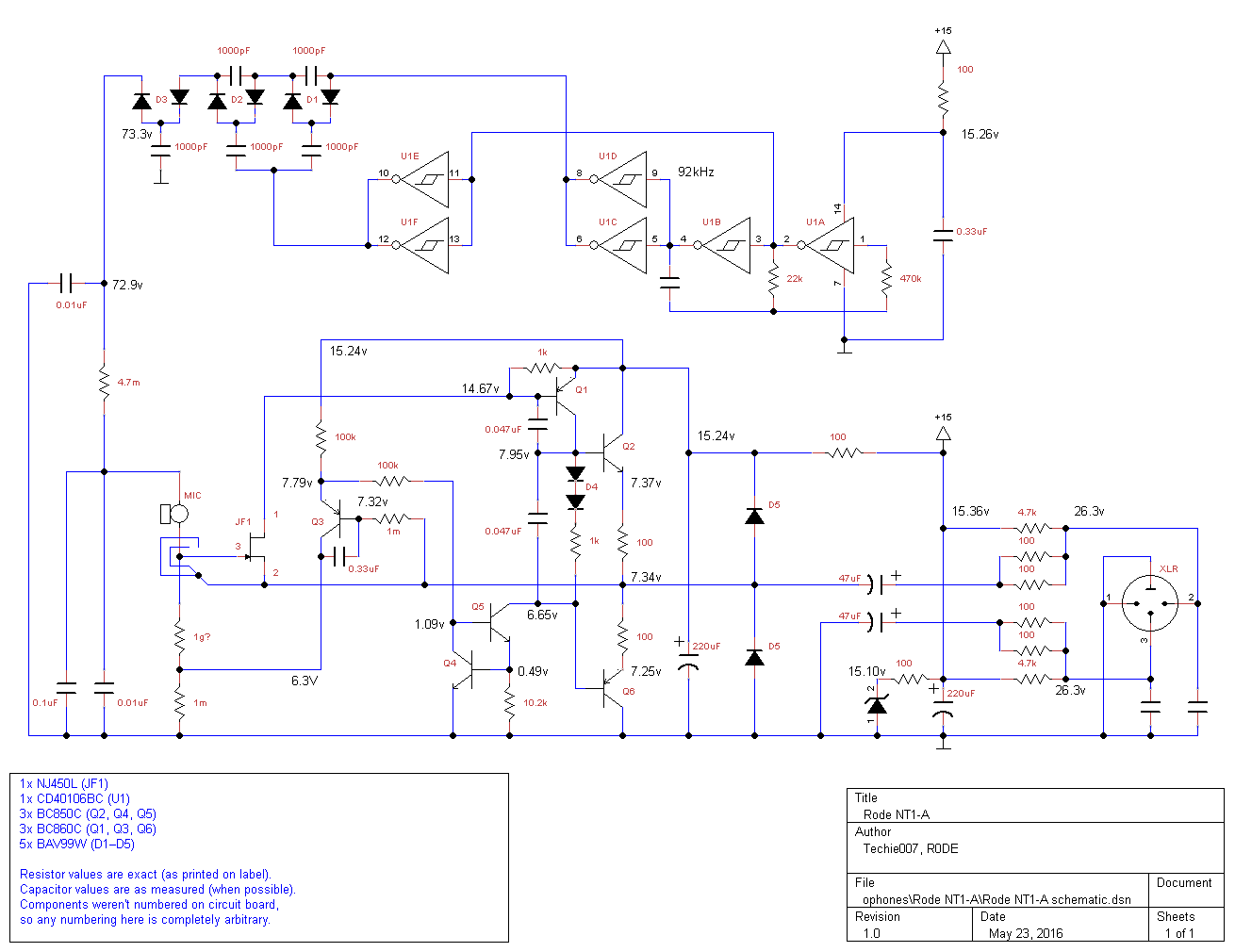
This schematic is for the newer, surface-mount version of the Rode NT1-A. The most shocking thing for me was to discover that the NT1-A is actually not balanced or even fully impedance matched, contrary to much of the hype surrounding this microphone.
This schematic is for the newer, surface-mount version of the Rode NT1-A. The most shocking thing for me was to discover that the NT1-A is actually not balanced or even fully impedance matched, contrary to much of the hype surrounding this microphone.
Err.rh! What makes you think its not "fully impedance matched"?Techie007 said:The most shocking thing for me was to discover that the NT1-A is actually not balanced or even fully impedance matched, contrary to much of the hype surrounding this microphone.
Techie007
Member
- Joined
- May 21, 2016
- Messages
- 8
Because when I touch a wire to the two XLR signal lines (one at a time) between the decoupling resistors and capacitors to introduce noise, I hear noise on the active signal lead that I don't hear from the grounded signal lead.ricardo said:Err.rh! What makes you think its not "fully impedance matched"?
Looks like there's nothing magic here. The input FET is indeed a VLN type, with the associated high capacitance, but in an LDC it is not redhibitory. The FET input capacitance is bootstrapped by NFB, and the feedback capacitance is not a big issue since the voltage gain of the FET is quite low in this configuration, so I would say the combination of minimal attenuation and VLN FET explains almost everything.bkdog said:I'm trying to figure out how they get the noise so low...
This node is grounded via a 47u on the minus leg; on the other leg, it goes to the output of the headamp, which impedance is not zero. That may explain the difference, or not...Techie007 said:Because when I touch a wire to the two XLR signal lines (one at a time) between the decoupling resistors and capacitors to introduce noise, I hear noise on the active signal lead that I don't hear from the grounded signal lead.ricardo said:Err.rh! What makes you think its not "fully impedance matched"?
Matt Nolan
Well-known member
You'd only get that test of yours to pass with a transformer output.Techie007 said:Because when I touch a wire to the two XLR signal lines (one at a time) between the decoupling resistors and capacitors to introduce noise, I hear noise on the active signal lead that I don't hear from the grounded signal lead.ricardo said:Err.rh! What makes you think its not "fully impedance matched"?
Techie007
Member
- Joined
- May 21, 2016
- Messages
- 8
Exactly! That's precisely what I meant by "not fully matched". It is nearly matched as the amplifier (when on) almost has an active zero ohm equivalent output impedance, but not quite. It rejects hum quite well, but not high-frequency noise. I think it was one of those "good enough" compromises that helped get this mic's self-noise so low. But it does help explain why I often have faint high-frequency electronic noise in recordings.abbey road d enfer said:This node is grounded via a 47u on the minus leg; on the other leg, it goes to the output of the headamp, which impedance is not zero. That may explain the difference, or not...Techie007 said:Because when I touch a wire to the two XLR signal lines (one at a time) between the decoupling resistors and capacitors to introduce noise, I hear noise on the active signal lead that I don't hear from the grounded signal lead.
Really? Wouldn't a balanced output transistor circuit (like what's in the NT2) exhibit an equal amount of noise when either signal lead is touched? This is what makes the XLR common-mode noise rejection work. Not that noise gets conducted to both leads by a transformer, but that both leads pick up the same amount and spectrum of noise due to fully matched impedance.Matt Nolan said:You'd only get that test of yours to pass with a transformer output.
Great work!
I moded few of these - for center terminated capsule version - there's pretty good option with jumpering one diode in DC converter.
Voltage goes down around 10V and microphone sounds much better. For edge terminated - depends on revision.
BTW i always measured little bit more than 75V of polarisation voltage.
Also there's something different on schematic, but currently i can't check it.
There was no double 47nF capacitor and definately there was one 33nF and also 100pF.
Matt Nolan
Well-known member
An impedance balanced output works because interference is picked up in both legs at the same time due to their physical proximity (very low loop area). The impedances need to be tightly matched so that the induced voltages are closely matched so that they cancel well at the balanced input stage at the other end. Your test is a bit off the wall by injecting interference on just one of the legs. That's not how interference pick-up works.Techie007 said:Really? Wouldn't a balanced output transistor circuit (like what's in the NT2) exhibit an equal amount of noise when either signal lead is touched? This is what makes the XLR common-mode noise rejection work. Not that noise gets conducted to both leads by a transformer, but that both leads pick up the same amount and spectrum of noise due to fully matched impedance.Matt Nolan said:You'd only get that test of yours to pass with a transformer output.
You have the RF pick-up problem because the output impedance of the driver stage is high at RF and causes an imbalance.
That's the limitation of most of the impedance-balanced circuits. But even the reverred Schoeps circuit is not perfectly balanced, since the output transistors are driven by different nodes. But what makes it so good is that the impedance of each leg is very low (less than 10r); as a consequence, the absolute value of the unbalance is also very low. Both these factors contribute to the excellent CMRR. OTOH, the NT1 has 50r resistors in each leg; combined with the increasing HF impedance of the active leg, CMRR is undeniably not as good.Techie007 said:It is nearly matched as the amplifier (when on) almost has an active zero ohm equivalent output impedance, but not quite. It rejects hum quite well, but not high-frequency noise.
IMO putting 50r resistors at the output is not very good practice; I know that mic pres are supposed to see an impedance of 150-200r, but I've never heard anyone complain about wrong response from a Schoeps Colette, on the contrary.
Don't forget that CMRR involves as much the receiver than the source. You may have an issue with your mic pre.But it does help explain why I often have faint high-frequency electronic noise in recordings.
moamps
Well-known member
The similar design (at output) is used in AKG 414b-tl2. I used these mics several times without any problems.
http://cloud.akg.com/8694/c414_b_uls_tlii_service.pdf
http://cloud.akg.com/8694/c414_b_uls_tlii_service.pdf
With its higher open-loop gain, the AKG probably has a lower output impedance.moamps said:The similar design (at output) is used in AKG 414b-tl2. I used these mics several times without any problems.
http://cloud.akg.com/8694/c414_b_uls_tlii_service.pdf
Anyway, a schematic doesn't show it all. The devil is in the details. Even with the resistors, AKG have additional ferrite beads, and the layout is probably as important as the schemo. The way teh capacitors are grounded can make a huge difference.
Techie007
Member
- Joined
- May 21, 2016
- Messages
- 8
Thank you. I'm pretty sure I don't have the center terminated capsule version. It's possible that my 10 megohm multimeter lowered the polarization voltage slightly during measurement.ln76d said:Great work!
I moded few of these - for center terminated capsule version - there's pretty good option with jumpering one diode in DC converter.
Voltage goes down around 10V and microphone sounds much better. For edge terminated - depends on revision.
BTW i always measured little bit more than 75V of polarisation voltage.
Also there's something different on schematic, but currently i can't check it.
There was no double 47nF capacitor and definately there was one 33nF and also 100pF.
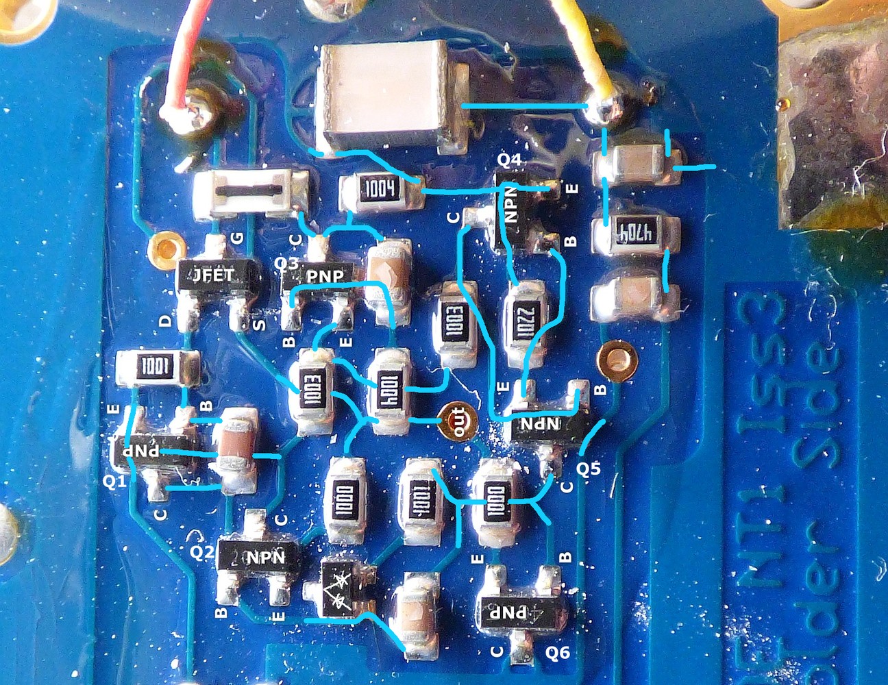
I would be glad to know of any schematic errors, and if there is a more typical way to layout this type of amplifier. I am quite confident that the "double capacitor" (between Q1 and Q2; between Q2 and Q5/Q6) is correct. However, their values could be anything, and I was suspecting that those values were too large. The capacitors were all measured "in-circuit", and I often had to try both polarizations on my meter to get an acceptable reading.
Perhaps another pair of eyes might help if I missed something? In the photo below, I have highlighted the traces that were hard to see:
From what i remember there was only one 47nF. I don't remember placement.
I measured capacitors removed from the circuit.
For edge terminated capsules - if your is really overbrighted (some are not so bumpy), try to remove last diode and replace it with jumper. Basic mod - and here's really audible - is to remove internal layer of headbasket. Works like a charm.
Change of the output capacitors values also make huge difference.
Techie007
Member
- Joined
- May 21, 2016
- Messages
- 8
With that recollection, my guess is that the capacitor on Q1 would be the 100pF one. I read several places of people improving certain microphones by replacing the surface mount capacitors with quality though-hole ones. Perhaps I should look into this? An added bonus, I'd find out the real sizes when removing the old SMD ones.
The frequency response of this microphone does bother me. I've seen it described as a "bright microphone", but I certainly would not call it that. Perhaps it sounds that way to people missing their HF (>10kHz) hearing. What I'm seeing is 3–6 dB peaks and valleys in the 2–8 kHz area (which makes it sound harsh), with severe rolloff as the frequency goes up to 20kHz (which makes it sound dull or lack crispness even though it's harsh). It seems to vary from recording to recording.
Won't shorting the last diode (in D3) just raise the bias voltage by 0.4V? That diode is really there to allow the last capacitor to filter the choppy booster output from power GND while allowing another capacitor to filter the now quiet output from audio GND without causing a ground loop between the two grounds. If boosting the bias voltage would help, I could try a slightly higher voltage zener diode. Replacing the 15V zener with a 17V one should raise the bias voltage from 70 to 80V. Can't really go higher than that since the 40106's absolute maximum voltage is 18V.
Based on several reports of significantly improved frequency response and "openness", I did try removing the thin wire netting inside the headbasket. Unfortunately, all this seems to have accomplished is making the microphone pick up a moderate 60 Hz hum. I was able to remove the netting without removing the headbasket, which remains fully attached and grounded as originally designed. The hum can be eliminated by placing the old netting over the back, sides and top of the headbasket, but it looks tacky. Speaking of which, the headbasket still looks like a serious acoustic limiter all the way around its lower half. I am wondering where I could buy a better headbasket inexpensively and solve the openness and new noise problem.
Changing the output (47uF) capacitors seriously makes a huge difference? What size/type do you like and how does it improve the sound from the original? I'm all ears about ways to improve this microphone short of spending $$$ (would rather put the money toward new mics and keep these). For instance, I've been thinking about Jfet options:
- NJ450L - NT1-A original for reference; 0.9nV, 35pF
- 2SK170 - Very similar, 0.95nV, 30pF
- LSK170 - Possibly good alternative; 0.9nV, 20pF
- LSK189 - If gains from real low capacitance will overcome higher noise; 1.8nV, 4pF
- MX16 - Perhaps best alternative; 1.1nV, 4pF
Have you measured this?Techie007 said:The frequency response of this microphone does bother me. I've seen it described as a "bright microphone", but I certainly would not call it that. Perhaps it sounds that way to people missing their HF (>10kHz) hearing. What I'm seeing is 3–6 dB peaks around 4–7 kHz (which makes it sound harsh), with severe rolloff as the frequency goes up to 20kHz (which makes it sound dull or lack crispness even though it's harsh). It seems to vary from recording to recording.
What mikes are you comparing it with?
Techie007
Member
- Joined
- May 21, 2016
- Messages
- 8
I have not done anything fancy like a white noise generator in an anechoic chamber for exact measuring, but I do have to seriously equalize all my recordings to make them not sound bad. I used to do it manually, but have since switched to software that analyzes at the overall spectrum of an entire recording and shapes it to a smooth curve, because the peaks on these mics vary from recording to recording. Probably because of the mic angle and distance changes from setup to setup. Keep in mind that I am usually doing ambient type classical music recording, so the overall spectrum of an entire recording is expected to be rather smooth.
What am I comparing it with? That's a tough one because these are my primary (and often only used) recording mics. They were my pick mainly because of low self-noise (I always record ambient but absolutely hate hiss). However, when I've used my AT3035s along with these, the AT3035s have a much less peaky sound with more HF. My camcorder (with great image quality but poor audio quality) sounds nice and flat compared to the Rode NT1-As. I have collaborated with other recording engineers on several projects (usually with the intent of nearfield+farfield recording), and I always ask for their originals when doing the final mixdown. Again, the same thing—their recordings are always brighter and clearer with no harsh peakiness, and often less bass. Yes, each engineer's system has its own sound and personality (which I occasionally have to correct), but these Rode NT1-A mics are quite unique and consistent with their unacceptable harshness, severe HF attenuation, and strong bass by comparison. If you need an example of what I'm talking about, see here.
What am I comparing it with? That's a tough one because these are my primary (and often only used) recording mics. They were my pick mainly because of low self-noise (I always record ambient but absolutely hate hiss). However, when I've used my AT3035s along with these, the AT3035s have a much less peaky sound with more HF. My camcorder (with great image quality but poor audio quality) sounds nice and flat compared to the Rode NT1-As. I have collaborated with other recording engineers on several projects (usually with the intent of nearfield+farfield recording), and I always ask for their originals when doing the final mixdown. Again, the same thing—their recordings are always brighter and clearer with no harsh peakiness, and often less bass. Yes, each engineer's system has its own sound and personality (which I occasionally have to correct), but these Rode NT1-A mics are quite unique and consistent with their unacceptable harshness, severe HF attenuation, and strong bass by comparison. If you need an example of what I'm talking about, see here.
This example is not valid IMO, because a distant recording is bound to be "duller" than a close one; it's just a matter of direct-to-reverberated sound ratio.Techie007 said:If you need an example of what I'm talking about, see here.
You don't mention what mics were used in comparison to yours, but you should make a comparison of your mics vs. a well-estabished standard, preferrably LDC, at the same position.
I would think that the main factor in your disappointment is the capsule itself, which for a reason you don't like. Personally I have gebnerally been disappointed with Rode mics; I can't criticize their level of technicity or competence in manufacturing, which is quite good, it's just I don't like the sound...
I have a feeling the reason why they are so often the subject of modding is just because they don't sound right to many people, proof that good measured performance is not a guarantee of subjective appreciation.
Techie007 said:With that recollection, my guess is that the capacitor on Q1 would be the 100pF one. I read several places of people improving certain microphones by replacing the surface mount capacitors with quality though-hole ones. Perhaps I should look into this? An added bonus, I'd find out the real sizes when removing the old SMD ones.
The frequency response of this microphone does bother me. I've seen it described as a "bright microphone", but I certainly would not call it that. Perhaps it sounds that way to people missing their HF (>10kHz) hearing. What I'm seeing is 3–6 dB peaks and valleys in the 2–8 kHz area (which makes it sound harsh), with severe rolloff as the frequency goes up to 20kHz (which makes it sound dull or lack crispness even though it's harsh). It seems to vary from recording to recording.
Won't shorting the last diode (in D3) just raise the bias voltage by 0.4V? That diode is really there to allow the last capacitor to filter the choppy booster output from power GND while allowing another capacitor to filter the now quiet output from audio GND without causing a ground loop between the two grounds. If boosting the bias voltage would help, I could try a slightly higher voltage zener diode. Replacing the 15V zener with a 17V one should raise the bias voltage from 70 to 80V. Can't really go higher than that since the 40106's absolute maximum voltage is 18V.
Based on several reports of significantly improved frequency response and "openness", I did try removing the thin wire netting inside the headbasket. Unfortunately, all this seems to have accomplished is making the microphone pick up a moderate 60 Hz hum. I was able to remove the netting without removing the headbasket, which remains fully attached and grounded as originally designed. The hum can be eliminated by placing the old netting over the back, sides and top of the headbasket, but it looks tacky. Speaking of which, the headbasket still looks like a serious acoustic limiter all the way around its lower half. I am wondering where I could buy a better headbasket inexpensively and solve the openness and new noise problem.
Changing the output (47uF) capacitors seriously makes a huge difference? What size/type do you like and how does it improve the sound from the original? I'm all ears about ways to improve this microphone short of spending $$$ (would rather put the money toward new mics and keep these). For instance, I've been thinking about Jfet options:
Anything that will improve its HF/transient response while also improving (or not seriously worsening) its sensitivity and noise floor would be great. Any thoughts or other Jfets out there I should be aware of?
- NJ450L - NT1-A original for reference; 0.9nV, 35pF
- 2SK170 - Very similar, 0.95nV, 30pF
- LSK170 - Possibly good alternative; 0.9nV, 20pF
- LSK189 - If gains from real low capacitance will overcome higher noise; 1.8nV, 4pF
- MX16 - Perhaps best alternative; 1.1nV, 4pF
You are little bit wrong about "bright microphone", because probably your revision is newer or just better.
If it's without black stikcer at the bottom (with model number and logo) you have a luck.
Most of these mics unfortunately bumped in hi mid aand hi freq.
I never had problem with hum after removing internal mesh. Originaly headbacket is also glued to the body, so there shouldn't change too much if you don't put too much glue.
Capacitors at the output - don't waste your energy for capacitor type - here value matters - try 68uF and 100uF.
If the low end go up overall tonal balance is much better and microphone don't sound so boxy.
Am using mostly low esr elna, panasonic, philips.
For midrange peak responsible is mostly headbasket and (also for hf) high polarisation voltage.
Measure voltage on several diodes and find the point where you can go down with the voltage.
You will get completely new microphone after all the tweaks but important is go down with polarisation voltage. You shouldn't notice much change in SN anyway - if so, always you can go back.
You can also change most of the caps for tht but i would keep RF caps as smd.