Varation on the Schoeps mic schematic front end?

GroupDIY Audio Forum

Help Support GroupDIY Audio Forum:

This site may earn a commission from merchant affiliate links, including eBay, Amazon, and others.

SSLtech

Well-known member
Joined
Jun 3, 2004
Messages
5,447
Location
Florida (Previously UK)
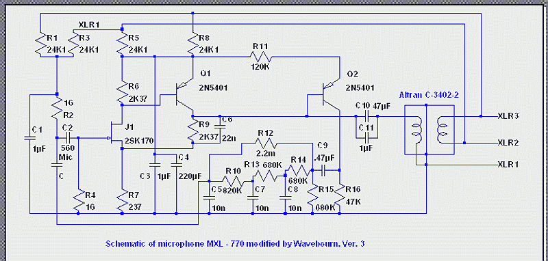
The Schoeps design as realised by the Scott Dorsey mods, and as similarly implemented in the SD MXL mics, uses two 1-gig resistors. -And a small capacitor in between.

The capsule has one side grounded.

As I understand it, the capsule's "diaphragm" connection is pulled up towards the polarisation voltage by one of the 1-gig resistors and the capacitor blocks any discharging of the DC polarisation voltage. The second 1-gig resistor on the other side of the small cap keeps the gate of the FET at 0Volts DC or thereabouts... a little below the FET's source voltage at any rate.

Am I right so far?

If so, could you not simply omit one of the 1gig resistors and the cap inthe middle, by simply moving the "backplate" part of the capsule up to the polarisation voltage, and connecting the "diaphragm" connection straight to the gate, with a 1-gig resistor referring it to ground for DC purposes....

Why wouldn't this work? -I mean presuming that there's no permanently physically grounded part of the capsule and you have free rein to do as you wish...

Or would it work?

Surely each 1-gig resistor saps the signal amplitude slightly, or am I missing something? Using 2 resistors raises the apparent parallel load on the capsule to 500MegΩ, instead of one resistor loading the capsule by only 1000MegΩ.

Keith
 
Hmmm... how much more of a problem would this be with this design? I'd have thought that the Shoeps version would also produce a pretty large switch-on THUMP!!!

Keith
 
[quote author="SSLtech"]Hmmm... how much more of a problem would this be with this design? I'd have thought that the Shoeps version would also produce a pretty large switch-on THUMP!!!

[/quote]

Forget it. It is a toy.
 
Whether or not the Schoeps implementation is a "toy" is not what I'm asking about.

You've said this cryptically several times before, but don't explain beyond describing subjective -and intrinsically rather biased- aural preferences.

What I'm asking about here is whether you can polarise a capsule in fron of a FET in the manner which I'm describing.

If using a FET with a 1-gig resistor and an externally polarised condensor capsule makes it a toy beyond hope, then I shall very probably have to sell all of my microphones except the U67... or is that garbage too? :wink:

I'm really looking for somthing different from an opinion on the Schoeps design... although,-just to keep score for everyone, Scott Dorsey rather admires the design, Wavebourn sneers at it every time it's mentioned... If I had to choose, whose advice would I take???

Anyhow... back to biasing a capsule! :grin:

:wink:

Keith
 
[quote author="SSLtech"]Whether or not the Schoeps implementation is a "toy" is not what I'm asking about.

You've said this cryptically several times before, but don't explain beyond describing subjective -and intrinsically rather biased- aural preferences.
[/quote]

You may SPICE it if prefer visual evidences. Don't forget to power through 6.81K resistors, add 50pf/meter of cables, and leakage capacitance between HF voltage converter and all transistors... And use typical IMD test signal, with something like 10KHz and 120 Hz. Increase 10 KHz (the capsule has 10 dB boost!) and enjoy the show. :roll:
You may modify the show adding 1.5-10K resistors between 2 and 3 pins of the XLR, with 47 uF non-polar capacitor in series, to simulate typical load impedance...
I guarantee you will be impressed! :D

What I'm asking about here is whether you can polarise a capsule in fron of a FET in the manner which I'm describing.

It may work if FET survives 48V on the gate when you apply the powering voltage (say, connecting the mic when +48 is on). However, you will need to swap 2 and 3 pins on XLR to preserve polarity. Wait... Most probably it will survive because of RC filters it powers through.

If using a FET with a 1-gig resistor and an externally polarised condensor capsule makes it a toy beyond hope, then I shall very probably have to sell all of my microphones except the U67... or is that garbage too? :wink:
I am not sure about the rest, but I still can't understand why the toyish design can be so popular. May be, because it is so cheap and easy understandable, and well advertised in an article in a popular magazine. ;)
I'm really looking for somthing different from an opinion on the Schoeps design... although,-just to keep score for everyone, Scott Dorsey rather admires the design, Wavebourn sneers at it every time it's mentioned... If I had to choose, whose advice would I take???

Anyhow... back to biasing a capsule! :grin:

:wink:

I am not responsible for Scott's preferences. Sorry. Did I answer your question about biasing? ;)
 
Well, thinking about it, you are creating a biased capacitor, the signal hitting the diaphragm modulates an AC signal through the cap and into the FET base. The cap serves to block DC and the 1G to ground of course drains the gate charge off but doesn't load the capsule too badly.

There are not many other ways to do this as simply as it's done here. I mean most mics use this type of front end stage. When I think of the schoeps circuit I think of the use of the fet as a phase divider and some follower transistors, not just the jfet/capsule/cap section.

So we state the problem, that the biasing voltage is much too high for the JFET gate for it to be applied directly. Current related problems aside, this would likely cause a punchthrough condition due to the creation of a huge potential difference.

The only other silicon way to do this that would be feasable would be to somehow track the DC input of the jfet and feed a nulling DC voltage back to the gate. This, however, would have to be a real precision circuit to get close to the performance of the much simpler circuit IMHO.

I guess we could use a tube as well, or maybe float the Jfet at the same voltage as the biasing so that the gate is never too high.. again not simple..

Wavebourn, how did you get around this?
 
[quote author="Svart"]
Wavebourn, how did you get around this?[/quote]

Around what? :shock:

Around mic/gate?

Classically. As you've described. Also, I power a capsule through a network with way long time constant.
I did not understand the question because 500 Gig is very high, too high to roll-off any valuable lows. Contrary, I've added a network stolen from Germans, to the body of the capsule, to roll of lows sharply.


Wavebourn-MXL770-V3.gif
 
Hi Keith,

Look at this schemo how they do it:

http://www.sdiy.org/oid/mics/MXL-V67.gif

You still have a second 1gig.
Hard to with SD because of capsule construction.

The only way I know of using one resistor (and no capacitor) is using a tube cathode follower.
 
You can do it that way - I've done it. But you need an RC filter on the capsule polarization that is significantly slower than the RC time constant of the 1G resistor and the capsule capacitance so you don't hurt the JFET. Ten meg and a 1uF should be good. It'll take 15 or 20 seconds for the mic to come up to full volume level.
 
look close at the real schoeps circuit Zebra had/has at their site. Many good notes on that schematic

The capsule is direct to the gate. All you lose is about 1V of capsule voltage. I guess some of my microphones should stop working.

Waveborn so be so dismissive of stuff how many microphones have you built or modded and done tests with?
 
[quote author="mediatechnology"]Of all the topologies I've looked at it, and Schopes clones, all are current sinks. I think that there's something to that. The rest are voltage sources. The Schoeps is a current loop interface with I-V conversion done at the preamp input's 6K81s.[/quote]
Good catch! -I never noticed that before...
[quote author="mediatechnology"]BTW: I'm now stocking 2G/2000M ohm resistors. So if you're concerned about 2 1G's in parallel you can now put 2Gs in parallel to reduce loading. This is a shameless plug and I make no apologies for it.[/quote]
ooh... I might take you up on some o'dem sometime!

Shoot me a PM with pricing if you would! -Thanks.

Dale,

REAL info! -Thanks!!!

Yes, I was giong to R/C the polarisation line, but I hadn't planned on making the time constant quite that long... I was thinking about killing RFI and 'line crackle' (this is a non-phantom design, with a separate polarisation line) but with your description, I think I'll add another stage of filtration, or simply change the component values to the sort of numbers which you gave as an example.

Does the actual Schoeps design have some sort of concentric-ring type of connecton arrangement, which can keep the SD capsule away from 0Volts, so that it can do that sort of thing...

Anyhow, I'm not building a Schoeps clone, so maybe wavebourn can sleep a little easier at night, knowing that the "evil virus" hasn't 'claimed another victim'...

None the less, I'm not really interested in discussing the detail of the Shoeps design, I clumsily chose it simply for being the most common example of the familiar FET input topology which I most commonly see.

Of course, with K67s and the like, the acoustic HF boost in the capsule means that you have to use two 1-gig resistors, becuase the feedback HF-reduction "de-emphasis" network is injected on the 'other' side of the capsule... see wavebourn's circuit for a 'plagiarised' example of some response-shaping... :wink:

Keith
 
Wayne

A little off topic. A person who I trust with sound told me the 12V version sounded better. So I looked close at the schematic I did the math for the output pair it was interesting. You can also think of the microphone as a voltage drive if you think of the 6.8K phantoms as the microphones emitter follower resistors.

The P50 fet used might be a part of the power supply voltage limit same as u87 and km8x circuits. Also look close at the DC to DC output to fet section there is a feedback gain reduction part.

My GUESS is the circuit was first made for SD capsules with a lower voltage out and 12V power and later adapted to 48V . Look at how low the input headroom?

There was the THE schematic here not long ago.
 
[quote author="Gus"]

Waveborn so be so dismissive of stuff how many microphones have you built or modded and done tests with?[/quote]

No need to make the same mistakes many times in microphones only to understand how distort emitter followers biased by lower current then needed when they work on low impedance, especially frequency dependent. If you want this particular topology to work well use custom load and especially designed phantom power supply, but in case of standard 48V phantom power it is impossible to bias emitter followers properly.
If you don't understand that you may go to Self's site and read the article, probably his authority will be enough if you don't understand technical explanations:

http://www.dself.dsl.pipex.com/ampins/discrete/ef.htm

However, D. Self on his page don't examine such stupid case like 20nF load of emitter follower biased by 6.8K resistor, his example is more common. 20 nF/6.8K would be great for AM demodulation. And it is what happens: rectification of high end of the spectrum that modulates the rest causing specific harsh sound; you've blamed a capsule, but it is not the source of the "Chinese Coloration". The source is toyish design of the amp. ;)
 
[quote author="Gus"]Waveborn I will not get into a pissing match.[/quote]

Do you mean math calculations, SPICE simulations, bench measurements? You are right, sometimes it is enough to look at schematics to understand what is wrong with the sound.
 
[quote author="SSLtech"] see wavebourn's circuit for a 'plagiarised' example of some response-shaping... :wink:

[/quote]

It is not a response - shaping, it is a pop-filtering. :cool:

I did not try yet this plagiarized feedback network, most probably I'll end with something better, as usual.
 
[quote author="Wavebourn"]
No need to make the same mistakes many times in microphones only to understand how distort emitter followers biased by lower current then needed when they work on low impedance, especially frequency dependent. [/quote]

For some reason you still don't get an idea that sometimes certain type of distortion in fact in some situations is desirable.

Once I posted a track on Gearslutz, recorded with Schoeps circuit. IIRC, you could not detect distortions under the question, so what is the point?
 
The circuit shown here is used by two popular brands of LDCs for their input stage. It uses only one 1G resistor and no coupling caps. The capsule sees a total bias of about 72 volts. The output is a source/drain follower circuit but does not use emitter followers with emitters pulled up to the phantom, the source being coupled to one output pin with a cap and the drain through a cap to the other output pin.

ldc_input_circuit.gif
 
Back
Top