Some observations about having built, repaired, upgraded and "skunkwors-ed" a few T4's over the last few years:
UREI (and Teletronix) T4s ARE matched unit-to-unit. Not to within 1% or anything (that would almost certainly mean a rejection rate in excess of nine out of every ten opto-resistors purchased: They do vary a LOT in same-batch production).
However, the LA-2a, LA-3a, BL40 and anything else that uses a T4 are all set up in feed-BACK limiting, which means that they do self-correct.
Onset of limiting (threshold) is largely set by the turn-on voltage of the EL panel, and this is a number which DEFINATELY creeps up with use.
If you compare a well-used T4 and a virgin one, the 'tired' panel will have a higher turn-on threshold, and a dimmer output-per-volt above that. A slightly relaxed compression curve is the net result.
okay, LOTS of people have built their own T4s WITHOUT matching the cells, and they'll notice that the GR diaplay and actual signal reduction doesn't track very well. Many don't even adjust R25 (I ALWAYS do!) to correct much of this, (Put a trimpot in there with croc-clip leads, adjust as you would the 1176, then when it's best matched, replace it with a fixed-value resistor of whatever value it turns out to be). They then assume that T4 optos don't track very well.
JBL/UREI used to include a pre-tested resistor for R25 in the white cardboard box with your T4. -I'm sure that David's have them. -They were most commonly taped to the T4 can, so they didn't get seperated. Lots of people didn't use them when they swapped T4's, they just either tossed them away, or added them to their resistor collection.
Now, Given that the LA-2a is in itself self-correcting (feed-back), and that the GR display CAN be matched for usable accuracy, Two LA-2a's will both compress at right about the same amount, threshold and ratio, given equal 'aging' of the T4s.
Here's the difference, given their 'Self-correcting' nature, they may be using
DIFFERENT AC control voltages for the same given signal gain reduction. -understanding that, there is a trimpot on the rear panel, which allows you to dial-down the unit which is producing more sidechain voltage signal. This DOES allow T4s to be brought eye-to-eye with each other. Any differences in curve should be comparatively small, and not truly significant.
In these days where we all have digital watches accurate to a fraction of a second per day, where VCAs can give you stereo tracking within
hundredths of a dB, we may think of these numbers as dreadful, but they were used on VAST numbers of the records which we loved. -Hell, the Mastering Lab (Doug Sax) had a modified pair of LA-2a's through which were passed some of the greatest-sounding pop/rock recordings in history. (The ML mods started with transformerless in & out... transformers were
de rigeur in broadcast installations, and only a fool would try a 'catalogue' installation without them, but the Mastering Lab was set up with short runs between KNOWN equipment interfaces, and this allowed them to extend frequency response and improve phase response and transient performance to an
unheard-of degree.)
So here's the deal: T4 optos were selected primarily for CURVE similarity. any large deviations or sudden 'kinks' in linearity are things you can't trim out with a single tripmpot, so
they are the ones which were rejected. -You can't -as I said earlier- make the optos "match" in the way you might first think, without first buying a hundred, and even then you'd be lucky to find two with acceptably constant, matching curves.
You
CANNOT buy up used T4s and compare them side-by-side in the same unit as a valid test. The GR tracking (R25) HAS to be adjusted, the rear panel limiter 'response' has to be adjusted (the LF -to-HF performance of differently-aged T4s also alters) and the stereo matching control (which -from memory, I seem to recall may actually be a potentiometer which turns down the limiter's OWN feedback control voltage, making it send MORE to the stereo link in order to achieve the same GR signal... hence matching it to the other... I'd have to review the schematic)
-But basically, to summarise it and say:
NOS t4bs are un matched and do differ in specs from t4 to t4.
...is to over-simplify it to the point where people may take a surface-skim read of your testing results and assume -VERY WRONGLY- that no matching was done in the T4s. -Also, buying up used T4s, they hardly EVER come with the matching R25 with which they were supplied: that means that you have to re-perform the R25 tracking test, or the test is VERY unfair.
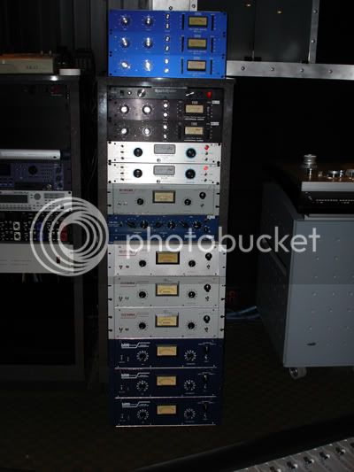
I've got LOTS of LA-2a's here... here's an example of Scenaria and I went on a mad LA2a-racking spree:
and I've stereo-linked MANY different combinations of them, and track-adjusted them QUITE satisfactorily, even using differently-aged T4s. I've also built my own T4s with various things: experimented with LED lightsources, -even nightlight optos- and I've definately found combinations -even using pairs of NSL and pairs of clairex- which don't trim-up to satisfactory matching.
(New line for this important summary)
However, ALL of the
genuine T4B's were adequately matched, with the exception of one which had been repaired by a technician who had graciously put a dated sticker on it to that effect. the different solder ages inside showed that most likely only one opto had been replaced.
I know this is a long read, but I do feel that before any statements are posted to the effect that there's no benefit (matching) to purchasing a NOS one, the statements should be tested FULLY for accuracy... Dripelectronics' experience does NOT tally with my own, and I do believe that David is not in a position to 'defend' himself without appearing to be 'pimping' a heavy investment which he made.
So I'll summarise by saying that I believe that Dripelectronics testing ethodology may be in error or perhaps has been very unlucky, because his results do NOT match my own.
Here's (briefly) how I measured the curves:
An excel spreadsheet with two lines line for each T4b under test.
A Neutrik A2 set to 1kHz, plugged into one channel of a Crown CE1000 amplifier, set to maximum gain, (at 0.7V-for-max-output rear switch setting). The output of the crown is wired to an octal-relay base, feeding the two EL panel conections. Two Fluke 87 MkIII's wired across the two pairs of opto terminals.
Plug in the first T4 after its been 'dark' for a day or two. Start with the Neutrik output muted. Sweep the output level starting from quiet-to-loud outputs in 1dB increments and note the two opto readings. Note the dB position at which the optos start to 'wake-up' (the threshold) and take a settled resistance reading for each opto, at every dB above that.
Enter the data into excel.
Plot a graph with the values. Look for kinks.
Do this over and over again, and check your measurements by throwing in a curveball, like a T4 which was home-made WITHOUT any matching, just random opto-cell selection.
Oh, and one point of David's; yes, T4Bs can and DO sometimes cause distortion. unplugging the T4 makes the distortion go away. I've seen it on several T4s, both home-made and NOS. Figures in the 1% reaion are not uncommon. -I talked to the engineer at the Mastering Lab who did the modifications to their units about my findings, and he said they had seen it too.
-Here's the odd thing though: you can make the distortion go away for a while: If you turn the GR completely off, measure the distortion at 1kHz 0VU unity gain, no GR for example. Then "blast" it with a +20dB burst increase for 3-4 seconds, and then switch back to the original 0VU test signal level. -You should notice that the distortion is now in the 0.1-to-0.2% range, but slowly creeps back up.
Again, speaking to the ML engineer, he said that they selected T4s, and that they too had noticed that the performance could be improved by what he called "washing" the optos with high level signal. (He called it "washing", I called it "Burning"... but it becams clear to both of us that we were referring to the same behaviour characteristic.)
Food for thought. -And something which other LAB users with LA2a's and access to a distortion analyser may be able to corroborate. -Not all T4s do it: about 10-15% in my experience. -With most, I was able to swap the GR and signal optos and find a less-distorted opto in the signal position. Again, because of the curve-matching, I they would still match, though R25 always had to be re-adjusted.
but does bring up the idea that the capacitor could be on it's way out , but that would just deal with the light panel working or not.
Absolutely ruled out: It does it with no gain reduction... Hopefully David canl corroborate that he's seen the same thing as I'm talking about.
Keith


