Switched Attenuator help for an RCA BC-2B

GroupDIY Audio Forum

Help Support GroupDIY Audio Forum:

This site may earn a commission from merchant affiliate links, including eBay, Amazon, and others.

Kid Squid

Well-known member
Joined
Jun 4, 2004
Messages
1,011
Location
Port Toilet, South Wales
'Allo Chaps,

After reading through various posts regarding Switched Brigded T Attenuators, I'm still covered in sand :oops:

Basically, I'm after a Switched Bridged T Attenuator - 2 pole, 11 way Rotary Switch, for a RCA BC-2B Mic Pre.

The attenuator will go between the secondary of the mic input transformer, and the grid of V1.

What do I need to know before I start, Then , How do I work out the resistances for the Switched bridged T,


Any help is appreciated,

Best Regards,

Steve :thumb:

P.S. Sorry to be so Naiive :?
 
[quote author="Kid Squid"]Then , How do I work out the resistances for the Switched bridged T[/quote]

try this
http://www.microwaves101.com/encyclopedia/calcattenuator.cfm

The Zo of the attenuator must be at least 10x the nominal secondary impedance of the mic transformer, to avoid loading.

You realize, of course, that putting the attenuator at the secondary will do absolutely nothing to prevent input transformer overload.
 
Dave,

[/quote]putting the attenuator at the secondary will do absolutely nothing to prevent input transformer overload.

I can see your point regarding overloading the primary of the input transformers, but, will other mic pre's that have transformers at the input, also suffer from this problem ?

sorry to be a pain in the arse,

Steve
 
they do, but one input transformer can handle a lot more level than another, so the decision to put the pad on the primary or secondary needs to be made on a case by case basis depending on what the primary can handle as level.
dave
 
If your input transformer, as an example, is 150:50K, you would need an attenuator that would reflect 500K to the transformer secondary, and 50K to the tube grid, if you didn't want to disturb circuit conditions as you adjust the attenuator. Even then, it still won't really work right, because the capacitive loading on the transformer will change as you attenuate. At greater attenuation settings, the xfmr will likely ring. If you must insert an attenuator at this point, save yourself some trouble and just use a 500k audio-taper pot.
Do you just want to be able to control the gain or the output level of the circuit? There are better ways to do it. Reduce gain by increasing the negative feedback. Control output level with a line attenuator such as the one I posted in another thread today.

If you want to pad down the input to avoid overload, use a U-pad between the mic and transformer. This page tells you how.
http://www.uneeda-audio.com/pads/
 
> a Switched Bridged T Attenuator ... between the secondary of the mic input transformer, and the grid of V1. .... Any help is appreciated

Here's my "help", though I doubt you will appreciate it:

Bridge-Tee is wrong for feeding a grid.

A Potentiometer is always the "right" way to pad into a grid.


Why?

What is the impedance of a grid? "Very very high, and unspecified." Or at least: much-much higher than the nominal impedance of the transformer.

But also: any resistance in front of the grid will add to noise. 10K will raise the hiss level, 100K will be absurd. You never want to add resistance in front of a low-level grid, as little as possible.

The pad's input impedance must be higher than the transformer winding. 100K will probably be a good value.

The output impedance of a plain bridge-T will be the same as its input impedance. If you need a no-loss position, the bridge-T can't have a lower (or higher) output impedance than its input impedance. You have stuck a whopping 100K in series with the grid, a LOT of hiss.

Now consider a 100K potentiometer. When loaded with a grid, the input impedance is always 100K, holding a constant load on the transformer, good. The output impedance can range from zero at infinite loss, to 25K at 6dB loss, to zero (plus transformer impedance) at no-loss. Bad around -6dB, but better than any T or O or H pad, and this is the best that can be done with resistive padding. The several "constant resistance" T O H pads add excess resistance on the output to meet the constant-impedance goal. If you actually need constant-resistance, you have to put up with that. But not in a grid, especially a low-level grid.

Anyway: Keep It Simple. Don't over-complicate. In this case it adds cost and noise and reduces treble response.

If you don't like rubbing-contact pots, build a switched potentiometer. Much cheaper than a switched T-pad.
 
Hello Chaps,

Input Transformer - UTC LS-10
50 - 600 ohm I/P
60Kohm O/P
Max Level - +19 dbm

Output Transformer - UTC A - 25
15 Kohm I/P
50 - 600 ohm O/P
Max Level - 30 mW

Dave, I would love to have an Input Gain, as well as a Output level !
regarding the Gain and negative feedback resistor values How would I work out the resistor values ?
regarding your output attenuator, I'll look into it :grin:
Would i still need an input pad, - how much attenuation ?

PRR - Thanks for your input - it is much apreciated. :grin:

Anyway: Keep It Simple. Don't over-complicate. In this case it adds cost and noise and reduces treble response.

If you don't like rubbing-contact pots, build a switched potentiometer. Much cheaper than a switched T-pad.

What value do you reccomend i make the Switched pot, how do i choose resistors - how would i calculate an audio taper -

Be Gentle - I haven't picked up a scientific calculator , since i finished college in '97.

In my job, there's not much need for calculations :?
I'm just a maintenance / repair tech in a steelworks !!! basically, as time is money, Faultfinding on a pcb can take a long time, so really, we change 'blocks' of circuit, then the pcb's are sent to the central works electronics dept for repair !
I have asked numerous times for a transfer to the electronics dept, But i think i'm consigned to a lifetime of Drone Work - Shit Happens :cry:
I have a growing interest in designing of equipment ( outside of Work ),
So,
I'm trying my best to keep with it,
I think I'm going to have to do a refresher course soon !!!
Steve
:thumb:
 
Adrianh suggested a schematics for controlling the attenuation after the input transformer on the RCA BC2B some months ago. Have a search and try to find it. I will try later, when I have the time..
 
http://quadesl.com/attenuator.html

http://music-club.rutgers.edu/headfonz/PotCalc.html
 
If you're going with a stepped pot between the transformer and grid, I think it'd be a good idea to arrange the last step to disconnect the pot from the circuit. That way, it won't be shunting the grid and loading down the input xfmr when it's not needed. Any resistance less than 600K is going to reflect to the mic as a lower-than-bridging input impedance.
 
[quote author="Kid Squid"]Dave, I would love to have an Input Gain, as well as a Output level !
regarding the Gain and negative feedback resistor values How would I work out the resistor values ?
regarding your output attenuator, I'll look into it :grin:
Would i still need an input pad, - how much attenuation ?[/quote]

Here's my suggestion for a flexible gain control arrangement for the BC2B.

1. Two switchable U-pads (10dB and 20dB) on the input, strictly to protect against overload and used only when the input signal is hot enough to warrant it.

2. Replace the 470k feedback resistor with a 120k fixed resistor in series with a 500k pot wired as a variable resistor. Replace the 0.22uF coupling cap with 1.0uF.

Since the plate of the second 12AY7 is working into the 15k (nominal) load of the output transformer, any value of feedback resistance around or above 150k will cause little additional loading of the plate. 120k in parallel with 15k is 13k, which isn't a major degradation. Label this pot "gain." The pot will vary the gain within about a 14dB range, admittedly small but still useful.

At max gain setting, you'll have 3dB more gain available than in the stock circuit. You'll also have 3dB less feedback margin to reduce distortion, but let's not even trouble ourselves with calculating all that right now. Try it and listen.

3. Build the first section ("Atten. 1") of my 600-ohm balanced attenuator and put it between the output transformer secondary and the output jack. Label this "output attenuator." This circuit will not produce thundering signal levels, so 0-10dB of attenuation should be plenty.

This should give you plenty of control over the clipping and output levels of the preamp without unduly compromising its performance.
 
Good Morning Chaps,

1st Thing - Absolute respect to you chaps for the help - it really means a lot :grin:

Rafafredd, cheers man :guinness: - i'll get on the case !

PRR - Thanks for the advice, and the working Pot Calculator , top stuff !

Dave - Thank you for sharing your knowledge regarding this pre, I'm learning all the time - Thank FxxK for the Internet, and the people that frequent it :thumb:

Anyway,

I'm going for what you suggested, a switchable balanced pad on input, before I/P tranny (10 + 20dB),
adding the pot in the feedback loop, and putting your 600 ohm attenuator after the O/P tranny.
with regards to the 500K pot, should this be a log / audio taper pot ?

Also, with regards to the 500K pot, I'm going to go for PRR's switched pot,
using the calculator, it asks, what is the total attenuation required.

I have no idea :oops:

Dave, how do you calculate the attenuation figures, for example the 10dB attenuation on the output level ?

sorry to be so green :oops:

Best Regards

Steve :thumb:
 
A 500K reverse-log would be best for the pot, but good luck finding one. Since you're in the UK, check with Omeg. I believe they offer one. A linear-taper pot will work fine but won't have as smooth a taper.

If you want to vary the feedback in steps, that stepped attenuator calculator isn't going to do you any good. That calculator figures out simple signal voltage dividers. With negative feedback, things get a little more complicated. Gain with negative feedback (in a noninverting circuit like your BC2B) is found by

G=A/(1+AB)

Where G is the closed-loop gain, A is the open-loop gain, and B is the fraction of the output signal that is fed back to the input.

So, you need to know the open-loop gain of your circuit in order to find the correct value of B to yield a desired figure of G. This can be found using load lines, but the procedure is tedious, especially since the dynamic load line is going to shift at different settings since the value of feedback resistor changes, thus changing the load on the plate.

An easier way would be to use the 500K pot and measure the gain change at extremes of rotation. Let's suppose it conforms to my estimate of 14dB. Since 2dB is about the smallest change in gain that you can hear, a 7-position switch with 2dB/step would make sense. Adjust the 500K pot and measure the output of the preamp. At every 2dB increase, stop, disconnect the pot from the circuit and measure its resistance. This will tell you the size of resistance you need for that step. It sounds tedious, but figuring it out on paper is even more tedious than that :wink:

You could also fart with it in a circuit simulator, but a) my own experience with simulators leads me to distrust them and b) I don't know of any readily-available models for the 12AY7.
 
I just thought of something: if someone was willing to provide me with a set of input and output transformers, I would be happy to build up a BC2B and work out the whole gain control issue, and post complete details for everyone to use. I'm just not willing to spend my own money for the transformers, especially the 15K:600 gapped output. I just bought a new car and I have payments to make. :wink:
 
It looks like you will have something like 4-5 mA of current throght the transformer winding. I´m acctually using a big, iron core, ungapped one without problems. The not so expensive LinxAudio 4:1 10k:600. I guess a cheap 4:1 EDCOR will do it.
 
Actually, if you were going to use an Edcor--ignoring for the moment the fact that it's ungapped and might therefore be unsuitable--they offer a model with the correct ratio of 5:1. It's the WSM15K/600. It's not listed on their website but, according to their tech, it is available.

I'm actually using a big, iron core, ungapped one without problems. The not so expensive LinxAudio 4:1 10k:600.

Did you measure low-frequency distortion? How much does the primary inductance drop with the DC bias?

You may not have noticed any problems so far, but that doesn't mean they don't exist. The preamp could sound fine with "typical" material but crap out with material containing a lot of low frequencies.
 
By the way, for those who missed it the first time, here are some nice color advertisements for the BC-2B console that I scanned from issues of Audio Engineering magazines from 1952. It's a big file... Right-click and "save as." Please do not load the file multiple times, since PRR was kind enough to loan the webspace and we don't want to abuse it.

6.5Meg PDF

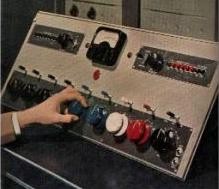
Here's a glance at the front panel:
RCA-BC-2B.jpg


Photos of the BC-2B and other old RCA consoles can be seen here:
Broadcast Archive Page
 
Hello Chaps,

Sorry i haven't been around this weekend - World Rally Wales GB has been through, One of my mates had a couple of weekend passes........
:green: :green: :green:

Anyway,

Dave - Thanks again for your input on this !, regarding Varying the feedback in steps with the 500K pot, I think i'll go for adjusting the pot for level changes of 2dB, then disconnecting, and measuring the resistance of the pot. something I never even thought about :oops:

Dave I can sort you out a UTC A-25 ( i've got a spare one ), but i have only one LS-10 !
If this can help you - I'd love it for you to work out the details on the circuit, Then it's another bit of education regarding the subject of attenuation/ gain in feedback loops!
I for one would be much appreciated. :grin:

Regarding the specs for the A-25,

Plate to Line
Primary impedance - 15 K
unbalanced D.C. - 8 mA
Secondary Impedance - 50, 125/150, 200/250, 333, 500/600
pri. resistance 1580 ohms
max level - 30 mW
-2 dB from - 40 - 20 KhZ

Nice pics BTW !

Best Regards

Steve :thumb:
 
I just thought of something: if someone was willing to provide me with a set of input and output transformers, I would be happy to build up a BC2B and work out the whole gain control issue, and post complete details for everyone to use. I'm just not willing to spend my own money for the transformers, especially the 15K:600 gapped output. I just bought a new car and I have payments to make.

Dave, Maybe I can Help You !

Dave I can sort you out a UTC A-25 ( i've got a spare one ), but i have only one LS-10 !
If this can help you - I'd love it for you to work out the details on the circuit, Then it's another bit of education regarding the subject of attenuation/ gain in feedback loops!
I for one would be much appreciated.

Regarding the specs for the A-25,

Plate to Line
Primary impedance - 15 K
unbalanced D.C. - 8 mA
Secondary Impedance - 50, 125/150, 200/250, 333, 500/600
pri. resistance 1580 ohms
max level - 30 mW
-2 dB from - 40 - 20 KhZ


Best Regards

Steve :thumb:
 

Latest posts

Back
Top