peter purpose
Well-known member
I have some, but only if you ask really nicely and you check back to see what 'score' means.


I haven't seen this behavior. The 'A' side of the switch is going to the sidechain input. At '0' the input is grounded, at '2' it is being fed to the sidechain. It sounds like there might be a big DC voltage from the output of the A1 doa? This would cause a sudden spike to go into the sidechain and trigger it to compress the signal. A DC voltage on the input was the first thing I thought of for the thumps on your output 'B' side switch as well, since the resistors connect each switch position, and effectively make the 'B' side of the switch a voltage divider. You can check the switch pretty easily - disconnect the input and wiper from the 'B' side, attach R64, and measure the resistance of the wiper to ground as you turn the switch. Verify that it matches the schematic.1) I jumpered sw5B sweeper to r64, and confirmed that the unit otherwise appears to behave properly. This kills the giant thumps since it effectively bypasses the switch section, so something is up in this switch deck. (I did put in the spacers from another switch, and it tightened it up mechanically, but not sonically) Specific question: With sw5B jumpered out, switching from '0' to '2' the unit mutes entirely, then comes back up. Is this normal behavior for sw5A, or evidence of other issues?
2) following dmp's advice on meter trim, I discovered relatively similar steps in meter/GR correspondence. What I don't see addressed anywhere, is what the attack control does to meter behavior. In this unit, a slower attack causes the meter to show greater gain reduction than it does at the stock (fastest) setting. As expected, the actual result of slower attack is that more transients pass through, and output level rises as expected. A 1M attack control does work, but does the meter misbehave because of it, or is this unit also funky in this way?
3) I aligned the GR meter following dmp's clues, with the ceiling control set to position 10. I then checked the measurements with it set on 2 and 20, and found that I got slightly less GR per LED on 2, and even less on 20. At 7 LED's in particular I measured -4.6dB GR on 20, -5.8dB GR on 2, and -6.3dB GR on 10.
")
peter purpose said:Second thing is what resistor I will solder on this resistor?
On the switch? 1/4w metal film are just fine.
jandoste said:peter purpose said:Second thing is what resistor I will solder on this resistor?
On the switch? 1/4w metal film are just fine.
Thanks Peter,
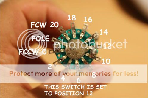
I meant what value of resistors I neeed to solder? I searching and already searched on all pages but I just found this picture :-X :-[
Thanks again!
http://www.mouser.com/Search/Refine.aspx?Keyword=271-9.1k-rcjandoste said:Hi again :
I'm sorry for my stupid question but I can't find on mouser 9k1 resistor so can I use 10k instead of 9k1?
Thanks for any advance.
cheers,
benlindell said:http://www.mouser.com/Search/Refine.aspx?Keyword=271-9.1k-rc
Awesome!Enter your email address to join:
