Art Pro VLA - Help me add input and output transformers!

GroupDIY Audio Forum

Help Support GroupDIY Audio Forum:

This site may earn a commission from merchant affiliate links, including eBay, Amazon, and others.

norman_nomad

Well-known member
Joined
Jul 27, 2005
Messages
115
Location
San Francisco
Hello all,

For fun I picked up some cinemag transformers for my Art Pro VLA compressor with the idea that I would use them to transformer balance the input and outputs. I'm doing this an experiment to see how it might change the sound of the compressor.

Here's a link to the transformer pdf's.
Input: http://cinemag.biz/line_input/CMLI-15-15B.pdf
Output: http://www.cinemag.org/output/CMOB-2.pdf

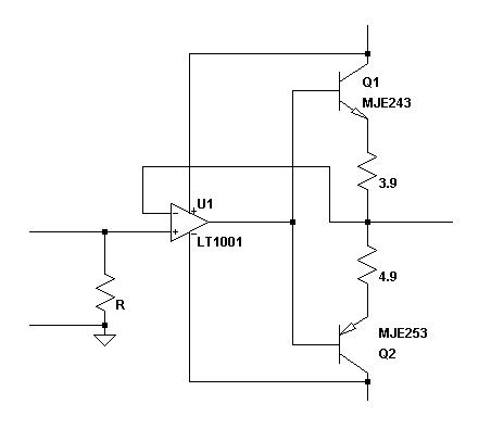
I added the input transformers successfully... I think. I essentially bypassed the TL072s and went straight to the main board. This works fine, but I loose 3db of gain. Not sure why. :? I attached a pic of what I did.

Art%20Pro%20VLA%20-%20Cinemag%20Input.jpg


But what I'm getting confused on is how best to add the output transformers. :?:

Can someone take a look at the schematic and tell me what they think?
http://www.blacklionaudio.com/art_pro_vla_schem.html

Specifically I'm wondering if I should have the output transformer follow the balancing 5532 or if I can bypass this somehow?

Sorry for the newb question, but I'm doing this to learn!
 
[quote author="norman_nomad"]
But what I'm getting confused on is how best to add the output transformers.
Specifically I'm wondering if I should have the output transformer follow the balancing 5532 or if I can bypass this somehow?[/quote]

Hi,
You may connect the output transformer directly to the opamps' outs. The output opamps cannot be bypassed here because you then lose the low output impedance buffer needed to drive the ouput transformer.

Regards,
Milan
 
[quote author="moamps"][quote author="norman_nomad"]
But what I'm getting confused on is how best to add the output transformers.
Specifically I'm wondering if I should have the output transformer follow the balancing 5532 or if I can bypass this somehow?[/quote]

Hi,
You may connect the output transformer directly to the opamps' outs. The output opamps cannot be bypassed here because you then lose the low output impedance buffer needed to drive the ouput transformer.

Regards,
Milan[/quote]

Thank you very much for your help!

So just to be clear, there is no good way to implement the output transformer directly after the tube stage?

I drew up this quick drawing.

Pro%20VLA%20Output%20Section.jpg


So if I gather what you're saying the opamps provide a low impedance output that the transformer needs.... so I'm to assume the tube output impedance coming directly before the opamps is too high to send directly to the output transformer?

Sorry for the simple questions.. but I'm still trying to understand all of this.. :oops:
 
[quote author="norman_nomad"]

So just to be clear, there is no good way to implement the output transformer directly after the tube stage?

So if I gather what you're saying the opamps provide a low impedance output that the transformer needs.... so I'm to assume the tube output impedance coming directly before the opamps is too high to send directly to the output transformer?
[/quote]

I'm afraid that with this particular transformer and tube topology there really is no way to implement the output transformer directly after the tube stage. If you look at the specs of the output transformer, you'll find that it needs a max. source impedance not exceeding 600 ohms in order to work properly. Any increase in the source impedance would result in increased distortion and degraded low frequency response.

In a nutshell, the otput transformer here should be connected to the outputs of the opamps (marked + and - OUT). 300-ohm resistors may be kept in the circuit although I'd throw them out if I were in your shoes.

Don't kill me for nit-picking but I believe that the current output opamp connections are not perfect for this particular output transformer, either. However, they will work so best leave things as they are.

Regards,
Milan
 
[quote author="moamps"][quote author="norman_nomad"]

So just to be clear, there is no good way to implement the output transformer directly after the tube stage?

So if I gather what you're saying the opamps provide a low impedance output that the transformer needs.... so I'm to assume the tube output impedance coming directly before the opamps is too high to send directly to the output transformer?
[/quote]

I'm afraid that with this particular transformer and tube topology there really is no way to implement the output transformer directly after the tube stage. If you look at the specs of the output transformer, you'll find that it needs a max. source impedance not exceeding 600 ohms in order to work properly. Any increase in the source impedance would result in increased distortion and degraded low frequency response.

In a nutshell, the otput transformer here should be connected to the outputs of the opamps (marked + and - OUT). 300-ohm resistors may be kept in the circuit although I'd throw them out if I were in your shoes.

Don't kill me for nit-picking but I believe that the current output opamp connections are not perfect for this particular output transformer, either. However, they will work so best leave things as they are.

Regards,
Milan[/quote]

Thanks Milan. Very greatful for the info. :grin:

Can you say briefly why the output opamp connections are not perfect for the cinemag output transformer I have?
 
I have a Dual Levelar that uses the same o/p topology. I have had the idea to do this for some time just for kicks, though I am only going to add the o/p transformer. I bought a pair of Edcor WSM600/600 thinking they would give this thing some good character. Haven't had enough free time to do mine yet. Too much DIY!

But I think the proposed plan is a good and easy one. You should short across the 300 Ohm resistors at the output...not needed with the transformer!

If you wanted to delete the opamps, I think you could use a 10k/600 transformer, but you'd have to get some extra gain in the ckt before. Loss would be too high with that much step-down. Somebody correct me if I'm wrong.

Peace!
Charlie
 
A2a is already set up as a buffer, disconnect R16 and connect the trannie at the junction of R23. R23 is also not needed as the signal can develop across the primary winding.
 
Good point Rowan, that detail had escaped me, but is obvious (now).

If a guy wanted to be a bit trickier, you could reconfigure A2b as an inverting follower and put it in parallel with A2a for 2x current.

Okay, maybe this can be accomplished this weekend! I'm glad you chimed in with that tip! Thanks!
Charlie
 
OK. So I finished this up last night and added the output transformer after the 5532 opamp and eliminated the 300ohm resistors.

This mod is really easy as you just ditch the whole in/out pcb board and wire everything to the 10 line ribbon cable connected to the main board.

Art%20Pro%20VLA%20-%20Input%20and%20Output%20Cinemag%20Transformers.jpg


I made some samples during the mod process. There are three samples. 1. Stock. 2. With input transformer. 3. With input and output transformer.

1. http://www.musicians-samples.com/Drums - Pro VLA - Mullard Tubes - Stock Input and Output.mp3

2. http://www.musicians-samples.com/Dr...rd Tubes - Cinemag Input and Stock Output.mp3

3. http://www.musicians-samples.com/Dr... Tubes - Cinemag Input and Cinemag Output.mp3

I hear a subtle difference in the low end a softening of the highs, but I'm wondering if you think I'd get different results if I integrated the output transformer per analag's suggestion.

Any thoughts are appreciated!
 
[quote author="norman_nomad"]
Can you say briefly why the output opamp connections are not perfect for the cinemag output transformer I have?[/quote]

Hi,
There's some useful info in the thread below:
http://www.groupdiy.com/index.php?topic=11102&start=0&postdays=0&postorder=asc&highlight=opamp+current+booster

To make a long story short, standard opamps are not intended to drive output transformers to their limits (and current is normally a limiting factor).

Analag's suggestion to drive the transformer non-simetrically is IMO slightly less effective than what I proposed (i.e. balanced driving). Anyhow, you can easily do some experiments and see which topology works best for you.

Regards,
Milan
 
[quote author="moamps"][quote author="norman_nomad"]
Can you say briefly why the output opamp connections are not perfect for the cinemag output transformer I have?[/quote]

Hi,
There's some useful info in the thread below:
http://www.groupdiy.com/index.php?topic=11102&start=0&postdays=0&postorder=asc&highlight=opamp+current+booster

To make a long story short, standard opamps are not intended to drive output transformers to their limits (and current is normally a limiting factor).

Analag's suggestion to drive the transformer non-simetrically is IMO slightly less effective than what I proposed (i.e. balanced driving). Anyhow, you can easily do some experiments and see which topology works best for you.

Regards,
Milan[/quote]

Thanks, this thread was very good to read.

From what I gathered, the 5532 does an OK job of driving a 600 ohm load. I assume that when you say that standard opamps are not intended to drive output transformers to their limits, you are refering to the fact that the 15v rails will be a limiting factor for the output current... What about swapping out the opamp for something else... maybe a discrete opamp? Will the 15v rails always be a limiting factor here?

I'm happy to be a solder monkey if you or anyone else has any other cool ideas for "upgrades" on this unit.

Thanks! :green:
 
The output current can be beefed up considerably by adding a current pump to the output of the IC.

Example.jpg


MJE171/181 complimentary pair with your 5532 should do the trick.
 
I tried adding the Edcors to my Dual Levelar last night.

First thing to note is that in my model, the output is driven from a quad opamp which limits choice of opamp quite a bit. I was using OPA4134...that doesn't work too well with the transformer...

I traded for TLE2074 and that seemed to work pretty good, but in both cases there is quite a loss of low freq info... I think the output coupling caps need to be changed to about 470 or 1000uF to match the low freq cutoff with the original circuit impedances...

One could loosely follow the schematic for the JLM hybrid to drive the transformer too. I think Rowan's suggestion would have a little cross-notch. Maybe not since it has the non-equal emitter resistors.

I tried driving the transformer single-ended and it sounded about the same, just a little less gain as one would expect. I think next I will try using the two output opamps in parallel to drive the transformer as I suggested before and increasing the output cap...

HTH!
 
Hey the non equal resistors is a typo, I was tired when I drew it up. The schemo was intended as an example of how to increase the juice to the transformer, it can be built out to perform at a higher level depending on how complex you want to make it.
 
>>>I was tired when I drew it up.

Well, it was really cool of you to make the effort! I thought you had snipped it from somewhere...

But to make it class a/b all we need to do is break the connection to the base of the PNP, insert a pair of 1N4148 in series with the cathodes toward the transistor, and then a resistor from the base of the PNP to ground...something on the order of 10k. Joe is using 2x 4007 and 8.2k on the Hybrid. Not sure why he is using HV rectifiers there but I don't think those a necessary are they...? I don't think we need the servo either, but we could use that other opamp that was driving the other side of the output if we really wanted it.

I think I will try the parallel opamp situation with balancing resistors and no cap first.

Thanks for looking at this with us Rowan. You too Milan!

Did you notice loss of low end on the VLA?

Peace!
Charlie
 
I didn't hear any low end loss that I would attribute to an impedance mismatch, but there is a highpass effect that the transformers are responsible for.

You can listen to the audio samples I provided and hear for yourself.

Analag, thanks for the pic; I may try to implement this as it seems easy enough.

Question: With the output gain all the way up on the VLA, I'm getting enough make-up gain for my needs. Is there a technical or aesthetic reason why I should want more output current?
 
>>>there is a highpass effect that the transformers are responsible for

Yes, different way to say the same thing. I don't want this much LF loss.

The issue of more current is in an effort to reduce unwanted distortion. Ideally, if you are going to get distortion, you want it to be from the transformer being driven hard. This is generally more pleasing than the output stage crapping out.

HTH!
 
[quote author="SonsOfThunder"]>>>there is a highpass effect that the transformers are responsible for

Yes, different way to say the same thing. I don't want this much LF loss.

The issue of more current is in an effort to reduce unwanted distortion. Ideally, if you are going to get distortion, you want it to be from the transformer being driven hard. This is generally more pleasing than the output stage crapping out.

HTH![/quote]

Fo sho. Transformer saturation would be preferred. :wink:

I posted samples so you can decide if there's too much low end roll off. I have examples of the unit stock, with input transformer, then with both input and output transformer.

I did a quick sine wav sweep measurement and it measures flat down to 20hz. The unit is being fed with a behringer ada8000.

I'm trying to figure out what I want to do next and then I'll post some more samples.

Any other suggestions are welcome.
 
Back
Top