8 Channel, 3U NEVE 1073 completed

GroupDIY Audio Forum

Help Support GroupDIY Audio Forum:

This site may earn a commission from merchant affiliate links, including eBay, Amazon, and others.
Sry...i kinda feel bad, in this case....cause i re-read your previous messages...and it does sound like you are helping yourself. There's been so many people tho....that just expect everything handed easily to them. I read hundreds of pages of thread info when i started my first build like, 5 years ago. No easy way out.

Quick search on the forum yields: http://www.groupdiy.com/index.php?topic=35422.0

That blue seems pretty decent, although it's only a two channel unit. Dan could definately do something custom.
 
Hi,

did some searching, but i have not found exactly what im looking for.

I am building 4 ez1290's, and am adding phantom, phase, and pad.  I have the inputs from the XLR wired to my phase and phantom switches.  But im not sure what the simple schematic for the PAD would look like, before i head off to input transformer land.

I am basically just building the JLM go between i guess.. i had the parts lying around, so i figured i would give it a shot.  Does anyone have a drawing of a typical 15-20db pad that will work here?


Thanks,

mike
 
Hey Mike. Quick search yields: http://www.groupdiy.com/index.php?topic=2370.0
 
Hey guys!

I'd like to wire an impedance switch for my pre's. I've read through all of the EZ1290 threads a few times, and took some notes. Here is what I understand:

One can install a DPDT switch that will switch between 300 (Parellel) and 1200 (Series). You get the 1200 impedance by tying the + of one primary to the - of the other and using the other + and - as the primary connections. In parallel you tie your +'s together and your -'s together and are left with the equivalent of one winding, 300.

Here are my questions:

1. Is the impedance switch wired from the input tranformer?
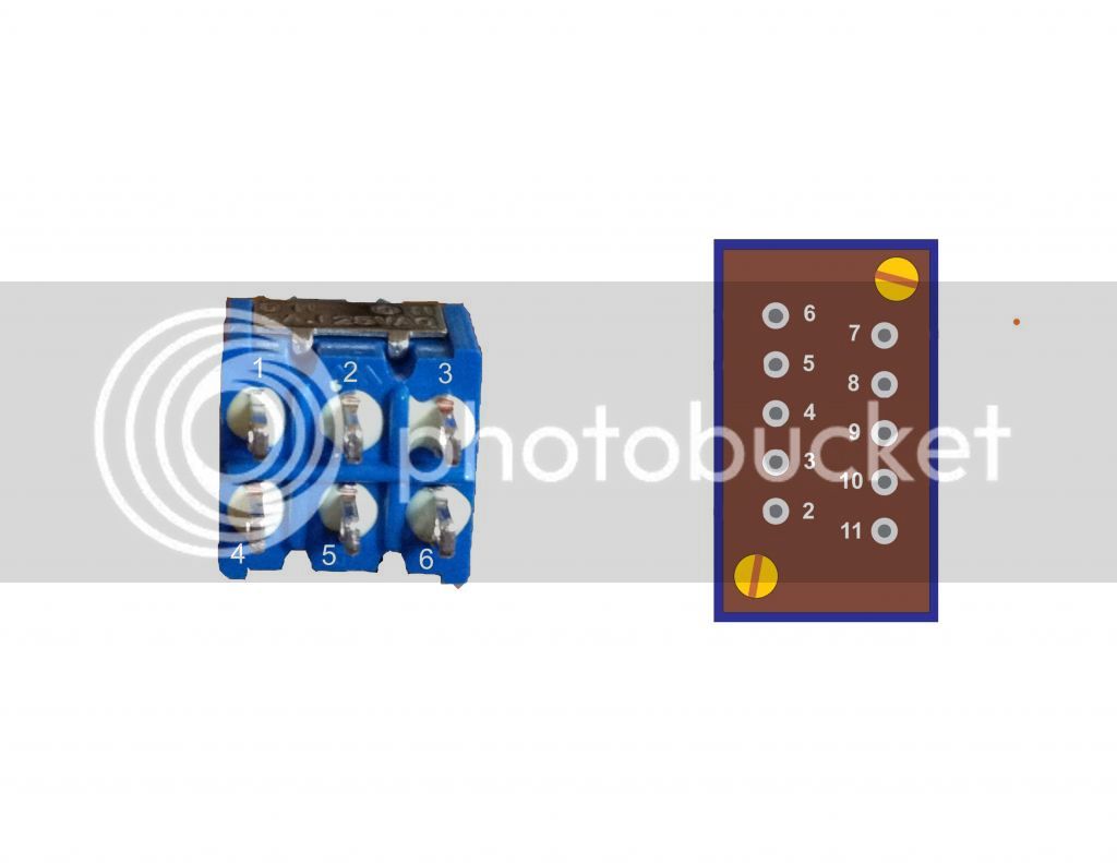
2. Would anyone be able to help me understand the process for wiring the impedance selector switch? Basically, I would like to understand which leg of the DPDT switch gets wired to the corresponding numbered input tranny post.

I'd really appreciate the help!
 
useme2305 said:
the impedance switch is basically explained in this pic:

Yep, I have that pic already, but I'm wanting to make sure I get it right. Basically looking for a impedance selector schematic for dummies.

I made up this pic, and would really appreciate if someone could simplify the wiring process, and tell me what numbers from the input tranny I need to connect to what numbers from the switch. I'd be happy to post the completed wiring diagram and post for others to reference.

ImedanceSwitchcopy_zps249a396e.jpg
 
That's great! Thank you!

Two more questions:

1. Do I still need to jumper between 8 and 9 on the input tranny, as per the assembly guide?
2. When using this with the Go Between, would I run the XLR wires into the Go Between first, and from there the impedance switch, or vice versa?

Again, really appreciate the help!
 
I see, so basically to protect against abrasions.

One more question, perhaps more important. I've finished wiring and stuffing all the boards, transformers, etc., but I have 10 OHM, 1W resistors from the BOM left over. What are these for? What did I miss?
 
...and if you used the JLM power supply you don't need it, cause it's built in.
 
JLM powerplant is designed to run Neve's, so i'm assuming it has it. I know the acdc, powerstation have it.
Might want to ask to be sure...or simply have a look on the board.
 

Latest posts

Back
Top