Emitter Current Noise Density

GroupDIY Audio Forum

Help Support GroupDIY Audio Forum:

This site may earn a commission from merchant affiliate links, including eBay, Amazon, and others.

Samuel Groner

Well-known member
Joined
Aug 19, 2004
Messages
2,940
Location
Zürich, Switzerland
Hi

Given hFE and rbb' of a bipolar transistor I know how to derive an estimate for voltage and base current noise. But how about emitter current noise? If we assume noiseless collector current is the emitter current noise just equal to base current noise or is there an additional noise source? Thanks for you comments!

Samuel
 
There's some extrinsic emitter resistance thermal noise which I've never seen tabulated, but the models assume the noise in the emitter current is due to the shot noise in the traversal of the potential barrier by charges flowing to the collector. The equivalent input voltage noise exclusive of the rbb' thermal noise (which is ~uncorrelated) is due to the shot noise in that current developing a voltage across the equivalent emitter resisitance. It works out to behaving as if it were a thermal noise of 1/2 the noise power of the equivalent emitter resistance.
 
It works out to behaving as if it were a thermal noise of 1/2 the noise power of the equivalent emitter resistance.
Thanks--so lets see if I get sound numbers: for a collector current of 1 mA we can assume an equivalent emitter resistance of 26 ohm. Which in turn is equivalent to 25.2 pA/sqrt(Hz), and half the power of that is 17.8 pA/sqrt(Hz). Now that's a pretty high figure compared with base current noise?

Samuel
 
I am interested in this topic and can't say that I follow the explanation close enough to get a sense for magnitude of this contribution.

Is this not already in conventional ein representations?

JR
 
[quote author="Samuel Groner"] Now that's a pretty high figure compared with base current noise?
Samuel[/quote]

It's not a current noise with respect to the base though, but rather an uncorrelated contribution to the equivalent input voltage noise, like having a resistor in series with r sub bb' with half the value of the equivalent emitter resistance.

Example: take a 2SC3329 with r sub bb' = 2 ohms, Ic = 13 mA; r sub e is about 2 ohms; equivalent noise resistance is like 3 ohms. Thus e sub n is about 220pV/square root Hz.

Manwhile with a beta of 600 I sub b is 22uA, and noise current density at high frequencies (well above ~1/f territory) is at least full shot noise of 2.7pA/square root Hz. Usually bipolars have i sub n rising well above full shot noise by the mid-audio band, so this is a bit optimistic. However, one can appreciate the desirability of high beta.

Optimal source Z is e sub n / i sub n = about 81 ohms. For higher source Z the optimal bias would be less than 13 mA. For lower Z, probably one is pushing it to have much higher Ic so paralleling would be in order (for example a transformerless ribbon amp application).

Needless to say there are a lot of ways to spoil this performance with noisy biasing, contributions of the next stage, B fields, and so on.
 
Is this not already in conventional EIN representations?
It is, but I'm interested in deriving a rough approximation for inverting input current noise of current feedback amplifiers, more specifically the usual instrumentation amplifier topology used for transformerless microphone preamplifiers. This topology (as probably any current feedback amplifier) suffers from an unfortunate drawback, namely that at low gains EIN is pretty bad--the reason for this is the largely increased current noise seen at the inverting inputs.

The figures I gave above are probably wrong (too high)--if I compare the published noise data of mic preamp ICs where I know the input pair collector current (e.g. THAT1510) to the theoretical figures I get way high values. Brad, could you elaborate?

[Edit, posts crossed: Brad, are we talking about the same thing? See my text above...]

Samuel
 
The current feedback amp analysis is tricky. I'm still not completely sure it's been done right as yet. However, a basic precept of noise analysis is that the noise performance of a transistor doesn't depend on its configuration. This statement is usually followed by a lot of "practical" qualifications about noise due to bias networks etc.
 
However, a basic precept of noise analysis is that the noise performance of a transistor doesn't depend on its configuration.
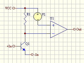
So just to make sure--if we have the following amplifier and assume noiseless bias and second stage:

cf_amp.gif


you're saying that the current noise at the inverting input is basically equal to that of the noninverting?

The current feedback amp analysis is tricky. I'm still not completely sure it's been done right as yet.
A quick survey of CF opamp datasheets indicates that the inverting current noise is 1x (AD811) to 35x (LT1259) larger than that seen at the noninverting input. Now that's quite a range... Typical is about 10x or 15x.

Samuel
 
Where does Q1 get its emitter current? If it's a noiseless perfect current source/sink, then e sub n has no effect (absent tiny base-width-modulation Early effects and capacitive couplings). But then we have no signal gain from the base either. The noise in the collector current is the noise in the base current, since there is no other place for the emitter current to go than to the base or the collector.

Start to add the external impedances of the real amplifier and then see what happens. And in particular, look what happens with the popular diamond-quad-style input configuration. Take account of the fact that the current fluctuations due to e sub n's wiggling r sub e's tend to subtract at the tied-together output junctions of the typical current mirrors that follow. That one had me puzzled for a while. It had bothered me that tying emitters together didn't perform a lot worse than providing each of N and P with independent current sources. There is evidently a tiny advantage to the latter but one IMO not worth pursuing.

It would be a good contribution if someone really did a thorough analysis. It must exist somewhere by now in the journals.
 
Thanks for your elaborations.

Where does Q1 get its emitter current?
Through the feedback resistor.

After a few calculations it looks to me as if noise from U1 (which modulates collector current) could easily dominate things for a real implementation--it might be worth selecting U1 for an OSI matching R1 for applications where low noise at low gains is needed.

Samuel
 
[quote author="Samuel Groner"]Thanks for your elaborations.

Where does Q1 get its emitter current?
Through the feedback resistor.

After a few calculations it looks to me as if noise from U1 (which modulates collector current) could easily dominate things for a real implementation--it might be worth selecting U1 for an OSI matching R1 for applications where low noise at low gains is needed.

Samuel[/quote]

When delivering the emitter current through feedback R there will also be an excess noise term in that R from that current, but I expect it to be modest too. I have used this biasing approach in both phono and mic preamps with good noise performance.

At the risk of asking a stupid question (who me), what would be a low gain application that benefits from this topology? At low gain U1 typically dominates noise as you mention. In noise analysis once you get several dB lower than a more dominant noise source the mathematical significance is much reduced.

JR
 
When delivering the emitter current through feedback R there will also be an excess noise term in that R from that current, but I expect it to be modest too.
I don't think that feedback resistor current noise matters--both ends are tied to low impedance nodes.

What would be a low gain application that benefits from this topology?
Balanced input stage for THD-analyser. Should have very low noise and distortion as well as high input impedance over a 0-30 dB (preferably 0-40 dB) gain range.

Samuel
 
[quote author="Samuel Groner"]
When delivering the emitter current through feedback R there will also be an excess noise term in that R from that current, but I expect it to be modest too.
I don't think that feedback resistor current noise matters--both ends are tied to low impedance nodes.


Samuel[/quote]

That excess noise term will be modest for typical circuit voltages and resistor types but any current injected at that emitter will look like a valid input signal and feedback path will respond to it. (I don't expect this term to be an important consideration but when counting angels on the pinhead it's there.)

For 0-30dB stage the internal opamp needs to be very low noise, since it will define noise floor relative to output and dominate unity gain. Discrete transistor front end defines noise floor relative to input, important at higher gains.

Stage could easily deliver better S/N at gain than at unity due to relative noise performance of best discretes vs. good opamps.

JR
 
That excess noise term will be modest for typical circuit voltages and resistor types but any current injected at that emitter will look like a valid input signal and feedback path will respond to it.
What I want to say is that there is no additional noise source (ignoring excess resistor noise) when using CF instead of VF amplifiers. It's just thermal noise of the resistor, if you look at it from a current side or voltage side.

This stage could easily deliver better S/N at gain than at unity due to relative noise performance of best discretes vs. good opamps.
I've not seen a configuration which shows this behaviour. If voltage and current noise of the amplifier is constant, output noise is always lowest at unity gain I'd say. But the improvement is indeed low--a few calculations with typical values indicate an output noise level increase of only 3 dB from 0 dB to 20 dB gain.

Samuel
 
If voltage and current noise of the amplifier is constant, output noise is always lowest at unity gain I'd say.
The SSM2019 datasheet (SSM2019.pdf) nicely illustrates this--check the top left figure on page 4. If output noise were constant, the graph would show a stright 45° line. If output noise would rise at lower gains the graph were--well, what's the correct term? Smothing with convex perhaps..? Anyway, you get it I hope.

Alternatively the datasheets for INA103, INA163, INA217, THAT 1510, THAT 1512 and AD620 all show the same thing.

Samuel
 
[quote author="Samuel Groner"]


This stage could easily deliver better S/N at gain than at unity due to relative noise performance of best discretes vs. good opamps.
I've not seen a configuration which shows this behaviour. If voltage and current noise of the amplifier is constant, output noise is always lowest at unity gain I'd say. But the improvement is indeed low--a few calculations with typical values indicate an output noise level increase of only 3 dB from 0 dB to 20 dB gain.

Samuel[/quote]

Precisely. Your observation confirms my point. If the output noise only increases 3dB from unity to +20dB closed loop gain, that indicates U1 and Q1 contributions are now at parity (they sum incoherently), but because of the 20dB more gain, S/N reflected back to the input has increased 20dB-3dB or 17 dB. So the S/N is indeed much better at this higher gain.

This is why I prefer to use unity gain stable opamps in the U1 position so I can keep noise gain there low. This is also why mic preamps routinely spec S/N at max gain since attention to detail, and very quiet opamps, are required for best performance at low closed loop gain.

JR
 
Well you're stating that EIN is better at higher gains--that's for sure. But S/N is usually output referred, no? Ratio of nominal output signal level to output noise, and that's best at lowest gain. At least it is what matters for my application.

In any case I don't understand why you are specifically mentioning this--that's the case with any topology I'm aware of and nothing special to this particular implementation. It's just that perhaps the degradation of EIN is more pronounced due to the large current noise at the inverting input.

Samuel
 
[quote author="Samuel Groner"]
If voltage and current noise of the amplifier is constant, output noise is always lowest at unity gain I'd say.
The SSM2019 datasheet (SSM2019.pdf) nicely illustrates this--check the top left figure on page 4. If output noise were constant, the graph would show a stright 45° line. If output noise would rise at lower gains the graph were--well, what's the correct term? Smothing with convex perhaps..? Anyway, you get it I hope.

Alternatively the datasheets for INA103, INA163, INA217, THAT 1510, THAT 1512 and AD620 all show the same thing.

Samuel[/quote]

? I never disputed that. Output noise and S/N are two different animals. If you wish to debate whether S/N sould be relative to output or input, have at it. In gain stages it's more useful relative to input while for unity gain it will be the same.

I am in full agreement that U1 is important for low output noise floor and thus optimal S/N at low gains for that topology.

For circuits requiring only modest maximum gains a DOA built from those 20dB (?) quieter Q1s might make sense. While no better (probably worse at +30dB) it could be measurably quieter at unity. Tradeoffs come in wrt GBW related distortion and phase shift. Choose your poison, noise or linearity? Of course you could always throw a DOA at U1 for maximum tweak factor.

JR
 

Latest posts

Back
Top