Line Mixing Console design with THAT ICs

GroupDIY Audio Forum

Help Support GroupDIY Audio Forum:

This site may earn a commission from merchant affiliate links, including eBay, Amazon, and others.
Richard Crowley said:
JohnRoberts said:
I guess we must agree to disagree about this. 
I wasn't seeking to disagree. I was trying to understand the (apparently subtle and/or not clearly defined) difference between usage.

Over the decades I have written about the differences a lot, and indeed there are few standards for usage and terminology. I even checked in the IEEE S-100 reference for definitions.

I am repeating myself but "balanced" terminology is associated with balanced impedance (same resistance) termination, and/or balanced signal which generally means two opposite but equal hot legs. So two versions of balanced and counting, but as i've already noted there are exceptions.

"differential" applies to the rest of the termination where a + signal is extracted relative to a - signal but two legs are not the same signal and/or same impedance.. Even single-ended terminations are technically differential but relative to the only two circuits, hot and ground.

When I call something differential I guess I mean not-balanced. 

Sorry if this is confusing, that is the nature of interfaces that evolved over decades.

JR
 
Richard Crowley said:
abbey road d enfer said:
I must add that I would not use the term differential for an output stage.
But in the general electronic sense (not specifically AUDIO) two output nodes with opposite polarity signals are "differential" are they not?  Or are we using the term "differential" strictly to explain how the signal is extracted at the destination?
I really think we should use the term "differential" only in regard to the electronically balanced input circuits. That's what I learnt at school. It really implies substraction (=difference). Indeed, cross-coupled electronically balanced stages include some differential essence, but should not be called differential IMO.
Just the same, calling an input balanced is very restrictive. It means that the input is not floating and both legs present the same impedance to ground. In particular, a floating transformer input is not "balanced", although it's actually very differential.
Ah!  I see what you are getting at. "Differential" implies ground-referenced signals, while "balanced" is a sub-set and/or has no such implications.
No, just the contrary. Balanced strictly means that both legs are referred to ground and that signal is equally split between them. A floating transformer input can be qualified as "differential", because it senses the actual difference between legs irrelevant of the common-mode voltage/impedance, but in the electronics world, differential is always active.
They are certainly not signal-balanced, but the signal is distributed between two legs that are not the ground, which, IMO, makes it differential.
I guess I was sub-consciously thinking of "differential" as two active, opposite-polarity, ground referenced nodes (as typical "transformerless balanced".)
I am myself guilty of using the word differential in that last sentence; it just adds confusion. the more I think about it, the more I conclude that differential output is an oxymoron.  :D
A notable exception is to be found in IC design, where a differential-output opamp actually has a relatively well understood meaning.
 
What a mess, my apologies in advance because this gets confusing.

OK from my copy of IEEE s-100 there are almost a page of "balanced" things,,, so here are a few.

#1 balanced circuit (signal transmission): This simply means a circuit with two electrically similar branches of equal amplitude but opposite polarity wrt a common reference, usually ground.

#2 balanced line (2 conductor waveguide): two transmission lines operating with equal but opposite signals wrt ground.

#3 balanced termination: ( 2 circuit) same impedance to ground in both.

#4 balanced 3 wire system. A 3 wire system where no current flows in the wire connected to supply neutral.

#5 balanced voltages : Equal amplitude but opposite polarity wrt ground on 2 conductors of balanced line.

From another page of differential stuff

#1 differential signal: the instantaneous algebraic difference between two signals.

I have paraphrased the definitions and omitted many that did not seem to apply to audio interfaces.

The numerous outputs and input topologies that we use do not fit neatly into categories.

I am perhaps too close to this since I focus on the pros and cons of the different design decisions, and I am frugal so do not embrace transformers for passing low level audio with good performance (I have used many transformers in installed sound products for background music). 

So in my judgement everything is differential, and there are a few different flavors of "balanced" that have costs and benefits.

Balanced impedance terminations provide benefit when exposed to common mode external noise sources, facilitating equal pick up for complete cancellation.

Balanced signal: Effectively 2 active signal stems with equal amplitude but opposite polarity. The most obvious benefits touted on spec sheets is 6dB more signal output from conventional IC voltage limits (that looks good to customers). There are also lesser benefits from the symmetrical signals.

Now the messy part, there are a number of different ways to make balanced signals, some that are more tolerant of mis-wired interfaces (like one hot leg shorted to common).  I am not man enough to try to name them all.

I will argue that there is not one single definition for balanced but several. 

When I say balanced I generally mean balanced impedance. When I say active balanced (output) I generally refer to balanced signal output with load compensation. When I use active symmetrical dual outputs I without load sensing I call them differential outputs, but that is not technically correct so I need to stop doing that. By definition they are balanced too, just more subject to customer misuse.

JR
 
> The numerous outputs and input topologies that we use do not fit neatly into categories.

+1

> there is not one single definition for balanced but several.

Long ago and far away, it was very clear. String two #6 wires coast to coast, drive them with center-tapped to ground transformers, that is BALANCED.

There are other ways to get similar benefits, some of them much cheaper, and almost every one of them claims the tag "balanced", if not in the ads then in slang. When many minds try "better" approaches, the field becomes muddy.
 
joaquins said:
Wasn't this a topic of a mixer or I miss read the title?

JS
Yes. That's the beauty of discussion. One starts with a project that bears expectations, based on a bunch of ideas that float in the air, some of them valuable, some of them flawed, and after some time, the very fundamental basics are discussed in a fruitful way. Isn't the subject of balanced connections not related to console design?
 
  Oh, well, I was just kidding, I love this kind of talk where the general/basic stuff about all off this get in discussion. I also was thinking that would be good to all of us understand each other properly and strait forward to set our standard about terms like this which are usually miss used/understood or controversial.
  In particular, I refer to 'balanced' as impedance balance, and two differential as opposite phase signal for (O/P) or difference between two signal (I/P). For signals not referenced to ground I use the term floating, (or not floating in the other case). But this is me, and my way to distinguish between each one of those.

JS
 
Hello friends, what's your opinion on resurrecting old topics that are semi-relevant to a new question? Better to just start a new thread?

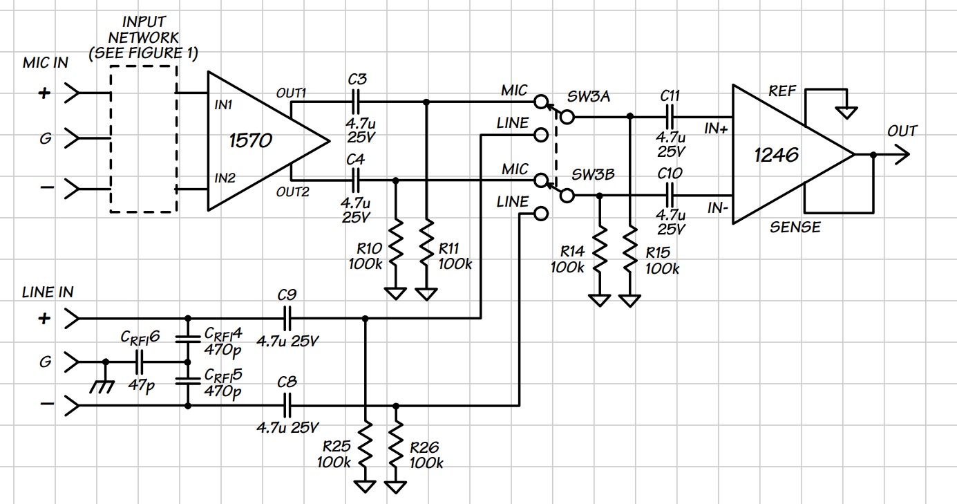
Anyway since this is on THAT IC's and consoles, I have a question concerning the below design note:

"AC coupling capacitors C3 and C4 in Figure 7 are only necessary when switching the output of
the 1570."


"AC coupling is required to eliminate clicking. AC coupling, by means of C3, C4, R10, and R11 block this DC
offset, helping to ensure silent switching...C8/C9, and
discharge resistors R25 and R26 block any DC potential on the line input. Finally, C10/C11,
and R14/R15, ensure that the 1246 input bias currents are not forced to flow through different
source impedances when SW3 is moved."


I'm pretty sure this means I can omit C10 & C11, as well as R14 & R15 if using it only as a line input, but I wouldn't mind a confirmation.

Thank you kindly for your input!

Qbie5CV.jpg


boji said:
I'm pretty sure this means I can omit C10 & C11, as well as R14 & R15 if using it only as a line input, but I wouldn't mind a confirmation.
You don't need C9/10 and R25/26 when there's no switch, just the RF protection caps.
Just like Fig. 4 in http://www.thatcorp.com/datashts/THAT_1240-Series_Datasheet.pdf
 
"C8/C9, and discharge resistors R25 and R26 block any DC potential on the line input."
I figured this meant some outside DC potential, not something from the switched sourcing, so even less parts than I thought!  Thanks Abby!
 
boji said:
"C8/C9, and discharge resistors R25 and R26 block any DC potential on the line input."
I figured this meant some outside DC potential,
That is exact. Now what is the risk of having DC on the line?
Decoupling DC is very important when there is some switching, because it creates annoying (and sometimes destructive) clicks.
The THAT circuit can withstand several volts without any effect on performance. Only a (very) defective source would do that.
 
I would agree you don't need caps on the input, but consider adding one on the output depending on what is feeding.  Also in addition to the input RF caps, input protection diodes can be a good idea.  They get tied to V+ and V- supply.
 
Thanks guys-- always helpful, always spreading the wisdom.

On 1200 vs 1240:  THAT 1240's are drop in replacements for INA's. Not so with 1200's, however 1200's appear to be their flagship super CMRR ic, but I don't find any language that says why except some hint it outperforms typical DLR's when fed poorly balanced signal inputs.  Long way of asking... if you had your druthers, 1200 or 1240?
Either would probably work well. It's job will be to receive sundry fx gear on aux bus insert returns, balanced or not.
consider adding [a cap] on the output depending on what is feeding.
Honestly, I don't fully appreciate what large caps off opa outs do.  ::) Lazy pleb guesses: Remove dc to tx? Steer NFB? Buffer output? Anywho the THAT ic will be feeding a 10k fader which then hits a booster, so... 220uF 16v seem acceptable?

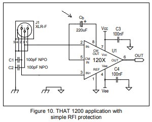
Also in the below application, Cb is 220uf.  That the same thing as a cap output you suggested?!?
4WbtfQ4.jpg


Also in addition to the input RF caps, input protection diodes can be a good idea.
Yessir! Seems wise- and I owe it to ya'll for explaining snub protection to me a few years ago.  8)  It's also recommended in the 1240 notes. 1200 notes suggest zeners be included.

 
boji said:
On 1200 vs 1240:  THAT 1240's are drop in replacements for INA's. Not so with 1200's, however 1200's appear to be their flagship super CMRR ic, but I don't find any language that says why except some hint it outperforms typical DLR's when fed poorly balanced signal inputs.
It says right in the THAT1200 datasheet above the equivalent circuit that it bootstraps the input making it's CMRR very high but without the noise of large resistors. So THAT1200 is definitely better than a simple differential IC even if the resistors are matched to perfection. Although I don't know if I would describe the 1200 as "super" CMRR because a transformer is better still. It's very hard to beat a transformer as long as it's big enough.

boji said:
I don't fully appreciate what large caps off opa outs do.  ::) Lazy pleb guesses: Remove dc to tx? Steer NFB? Buffer output? Anywho the THAT ic will be feeding a 10k fader which then hits a booster, so... 220uF 16v seem acceptable?
I think what john12ax7 was saying was that if you leave out the input caps, then you better have something to block DC downstream just in case the source does have DC.

You don't need 220u into 10K. I would use a large cap just to minimize low frequency distortion. But if you know the load is 10K, then 22u would be fine. Honestly 2u2 would probably be fine too but size and cost wise, 22u is not much different than 2u2 so you might as well design for 22u and worry about it later.
 
Yes I meant a cap connected to the receiver output,  pin 6 of fig 10 you posted.  Since you would attach a fader,  that is a classic reason to use a cap,  to prevent DC on the fader (and scratchy behavior). The value would depend on the load,  essentially 10k in parallel with whatever else.  47uF would be plenty for 10k load.  For voltage look at worst case, then add some margin.  So at least 25V cap rating for 15V or 18V rails, more if something  like +15V on one end with -15V on the other could happen. Bipolar cap since polarity could go either way.

THAT 1200 specs better than 1240 for CMRR. Is the extra cost worth it? Hard to say. I would lean towards simpler for an aux return in a known environment,  others may disagree.
 
The fires didn't reach where I'm at,  but the air was really bad, so stayed inside the last few days.  Think things are finally getting contained.
 
boji said:
On 1200 vs 1240:  THAT 1240's are drop in replacements for INA's. Not so with 1200's, however 1200's appear to be their flagship super CMRR ic, but I don't find any language that says why
Remember that in a studio environment, balanced connections are there to break ground loops. For years many console manufacturers relied on the quintessential one-opamp differential amp which, even using 1% tolerance resistors, may not have better than 30dB CMRR. It's only when IC solutions became available and affordable that CMRR increased significantly, but it was more a side-effect than a request.

except some hint it outperforms typical DLR's when fed poorly balanced signal inputs. 
The most poorly balanced source is an unbalanced one. If a basic differential amp (used as remote-ground sensor) does not cut the mustard, what studio users have done for years is using a balancing unit.
 
Edit: Forgot to say thanks abby for the above reply!

I'm ashamed  to admit my ignorance on this one, but, what's the standard output of rack gear? +4dBu?
The reason I ask is perhaps the THAT 1200 with a gain of -0dB is not the right choice...

Anyways, while we on the topic of boneheaded questions (I apologise in advance):
Calculating the gain of an ACN network is simply the feedback resistor divided by the bus resistor choice correct?
In a different thread, Ian helped Humner determine what bus resistors to use: "Under these conditions, the gain is just the value of the feedback resistor divided by the input resistor."

I know the feedback resistor on the 1st stage of the ACA is 28k. Bus channels use 47k.
Does this mean it's simply 28/47 or a gain of ~0.6?

One last thing- am I to add a 47k bus resistor to the end of the bus before going into the ACA or are only the channel's resistors to bus all that's needed? I am about to fire up the aca on 8 channels so I suppose I will find this out soon enough...


Latest posts

Back
Top