Test equipment needed for compressors

GroupDIY Audio Forum

Help Support GroupDIY Audio Forum:

This site may earn a commission from merchant affiliate links, including eBay, Amazon, and others.

Kid Squid

Well-known member
Joined
Jun 4, 2004
Messages
1,011
Location
Port Toilet, South Wales
Hiya Chaps,

I don't normally post in the Drawing Board, as I have very little knowledge with regard to electronic theory, and design, but I am slowly getting my head in to it.
Firstly, a million thanks to the guys that have helped me with the digestion of information within these electronic walls - you know who you are , and I don't want to embaress anyone :wink:

Right, I've built a couple of the G76's, GSSL's, Forsell opto's and a couple of LA2a's,
But I 've got more questions, with regard to the various test equipment needed for testing various compressor parameters, Attack and release in particular. I'm thinking it is something to do with a pulse being fired , from some generator, and somehow, picking this up in the GR amp, showing it on a scope. How would i do this ?, I've had a good look through the metas, and done quite a few searches, but I can't find much.
I'm sure that these questions have been asked before, and have been answered with very detailed info tho :oops:

I'm very curious about this, and there's no-one I know (personally)can answer this (these) questions.

I have got a dual trace scope, and a Signal generator with an external sweep input (don't know how to use the sweep tho :oops: )

Don't hold back, as the more I read, the more I understand !

Iechyd Dda

Steve :thumb:
 
There is no agreed standard to measure attack and release times in compressors between manufacturers.
Read PRR's and Ted Fletcher's posts here:
http://www.groupdiy.com/index.php?topic=10215
and also here:
http://www.rane.com/pdf/ranenotes/Dynamics%20Processors.pdf

chrissugar
 
Back when I was designing companding NR and compressor/limiters, I made my own tone burst generator. Basically a glorified gate circuit, that would gate some other sine wave or signal source as desired.

It had several adjustments, 1) a repetition rate for time between gating on events, 2) a duration for how long it stayed on each time, and 3) a mix level so I could set a variable crest factor for the burst height vs. baseline level. An important refinement is to only gate the sine wave on and off at zero crossings, preferably only gating full cycles so there is no DC component introduced. It was also useful to bring out a gate logic state signal to use as a scope trigger.

While I am a strong believer in measurements to qualify circuit performance, when dealing with such dynamic gain manipulations there is no replacement for lots of listening tests. You can teach yourself what the raw gated sine wave sounds like, making it easier to cull out artifacts introduced by gain elements, and optimizing time constants.

I don't have a schematic handy (I designed mine back in the '70s), but basically converted sine-wave input to a square wave, and used that to clock a 4013 cmos FF in combination with on/off timing logic. A simple J-FET shunt executed the actual gating.

JR
 
Do you have a DAW? One idea would be that you could literally edit together some tone burst "tracks" similar to what J.R.'s box output, including a trigger track output to drive the scope...
 
Cheers lads :guinness:

Much appreciated for your hint's, tip's and guidance.

Chris - thanks for those links mate , Da Iawn :guinness:

John - Thanks for the information regarding my question, basically I'd like to 'measure' whats going on electronically and visually, with regard to the side chain amps, in particular the attack and release waveforms, just curious , like :wink: and also, how would i set this up on a scope ?
Regarding your tone burst generator, Thanks mate, I'm going to have a look at a few circuits this afternoon, and try and get my head around the electronics. ( I can get my hands on a mate's modular synth, and I'm sure that there's all manner of gating, squre wave's etc - but will the pulse duration be 'short' enough ?)

It had several adjustments, 1) a repetition rate for time between gating on events, 2) a duration for how long it stayed on each time, and 3) a mix level so I could set a variable crest factor for the burst height vs. baseline level. An important refinement is to only gate the sine wave on and off at zero crossings, preferably only gating full cycles so there is no DC component introduced. It was also useful to bring out a gate logic state signal to use as a scope trigger.

While I am a strong believer in measurements to qualify circuit performance, when dealing with such dynamic gain manipulations there is no replacement for lots of listening tests. You can teach yourself what the raw gated sine wave sounds like, making it easier to cull out artifacts introduced by gain elements, and optimizing time constants.

I don't have a schematic handy (I designed mine back in the '70s), but basically converted sine-wave input to a square wave, and used that to clock a 4013 cmos FF in combination with on/off timing logic. A simple J-FET shunt executed the actual gating.
Thanks a lot , again , John for the top reply :thumb:

Samuel - This is the exact thread that I can remember seeing, also, I think Rowan (analag) posted similar waveforms, with regard to his poor mans 660 / big daddy 660's, but I can't seem to find where I put the links :cry:
Crusty - Got a digi01, but got no clue as how to set it up for this.
how long should the tone burst(s) be ?
Sorry , again for my lack of knowledge - But I am trying !

Also - regarding the sweep input on my sig gen, this would be used for testing frequency response?, how would I ramp it ?, would I use a long timescale sawtooth wave to do the gubbins ?

anyway chaps, I got to dash, I'll be back a little bit later.
Thanks again.

Steve :thumb:
 
There was a burst generator unit (quite similar to described by John) in Elektor Electronics in 80's. I built it and it worked fine. I tested peak programme meters and limiters with it. Today it is probably easiest to use computer soundcard.
 
PeakLimitingAmpTestBlockDiagram.jpg


30dBGR.jpg
 
I looked around my lab and couldn't find my old burst gate, but I can give a little more specific design advice. IIRC I used a quad opamp, 1 JFET, and 1 CD4013 d type FF.

I probably ran the whole circuit off a single supply to accommodate the cmos FF. One opamp was configured as a simple comparator to convert the sine wave into a square wave. This square wave was then used to clock the FF. This would insure that the gate always triggered on zero crossings and always going in the same direction so there was no DC component generated by the gating,

A second opamp section was set up as an astable multi-vibrator. A resistor from the output to the positive input, with equal value resistors to +V and ground provide hysteresis while steering diodes and two pots feed the output to a capacitor connected to the - input establish adjustable on times and off times. The output of this astable is connected to the FF data input.

The Q or Qbar output of the FF is connected to the gate of a JFET, whose drain is cap coupled to the junction between two equal value input resistors feeding an inverting opamp.The FET Source connects to ground. Running the circuit from a single + supply works with a P-ch JFET. A N channel could be used by running the circuit off a single - supply instead.

Finally another pot wired as a volume control feeds an ungated input to the inverting opamp, so you can mix in a dry, ungated level. If you want you can put a pot in the inverting amp feedback path for a master volume control.

I hope this all makes sense, it really is pretty simple and very useful for evaluating dynamic processors.

JR
 
Thanks for the diagrams Dave. Good thread.

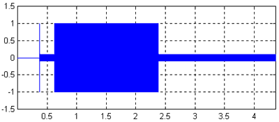
In the diagram the typical input waveform is a sine wave with its amplitude varied at zero crossings by a square wave like pulse.

The length and amplitude of which is user specified?

The pulse signal is used to create sine wave bursts to trigger compression and the pulse is also fed to the ext. trigger input on the scope to ensure timebase sync between the output waveform and the trigger?

Enabling you to measure attack and release times from the scope waveform?

What would be useable pulse lengths and amplitudes for the sinewave?

Do you set the compressor threshold to produce max gain reduction (say 30dB as picture) on a signal say, 0dBu which is your max source wave amplitude and then reduce the sine wave below that to not trigger compression and then bang it into the compressor upto 0dBu at a rate defined by the trigger?

If one was to do this in the PC, could you make a source wave form that is a sinewave burst and a pulse trigger that is sample accurate sync'd to the sinewave...feed the two out of diff. outputs, sine to the compressor under test and the pulse to the scope ext. trig...

Hmmm

Is it best to measure attack time as the duration taken to reach a specified amount of G.R or some other value?

Cheers Tom
 
I made my burst gate adjustable over a pretty wide range. I didn't use this to measure attack/release times, as much as come up with a wide range of test signals to better reveal and correct spurious artifacts in gain cells or VCAs. While it may be a little difficult to zero in on control voltage feed-through on a complex musical waveform, with a well defined burst you can see and hear it to more easily correct it.

While extremely short burst on times are not very useful, you can gather from the typical ranges of attack and release time adjustments that attack is more of a short term phenomenon and release longer term. I found burst off times needed to be quite long to really insure a compressor was attacking from a fully released state on the next burst.

JR
 
This is from memory but IIRC burst on-time was adjustable as short as low mSec range as long as maybe 200 mSec, burst off-time maybe as short as tens of mSec and as long as 1+ sec. Note: the shortest burst on-time can never be less than one full cycle due to how the FF is clocked, so a low frequency sine wave, gated shorter will just play one full cycle.

You can also do some interesting stuff like gating 20 khz, where you won't hear the signal (at least I won't) , but you will hear any artifacts of compressor or whatever processor you are testing.

JR
 
Right so 1mS for 1kHz sine wave test is the fastest burst on time.
If I were to make test wav. files then the burst opens at the nest zero after a full cycle....burst can stay on up to 1 secondish but could be shorter.

Have I understood correctly RE signal amplitudes and threshold settings?

-Tom
 
Yeah thanks Brad.

How much amplitude difference would be useful between the two-states?

Enough to ensure the signal is well below the threashold of compression in the off state and enough to put the compressor into heavy gain reduction in the on state?

Cheers Tom
 
> The length and amplitude of which is user specified?

"Player specified".

What do you really want to do? Control speech/music.

What are likely problems?

Low average level with a few BIG vowels/notes which blast. The blast/average ratio may be a few dB for a guitarist who almost has finger control, or many dB for a young opera singer who can find her resonances about 1 note in 10.

The real test is real music. And using your DAW, you can compile clips of passages which want limiting, and try them rapidly. (In ye olde days, I didn't get a fair opinion on a limiter until some hours of records and months of actual performances.)

But for reference testing, I'd think 10dB 20dB 30dB pulses would be useful. I really hate to hit 10dB, but this should reflect what's happening at lesser GR. Much pop music from un-smooth performers can stand a heavy hand, even 20dB when the banjo pick slips. 30dB is obscene, but I like to know if a limiter will get "impolite" when I'm told "this is soft" and the opening note is a percussion orgasm. (Had a piece which was 15 minutes of whispering punctuated by 7-foot bamboo rods Whacking the stage.)

Bring up the limiter input gain so the low tone almost budges the GR needle off "0". Roll the high tone and see what comes out.

For my safety limiting I never have Attack more than a few mS. If the idea is to hold drums down to 200% clipping, you may want 100mS attack. That tends to be exponential so you want a longer tone. 100mS-1,000mS seems fine. Depends some on your capture tools.

I tend to long release for musical dynamics, several seconds. Effects and low-quality speech can use short release to pull-up weak notes/consonants, 100mS or less. The tail of low tone after the high tone should be several times longer then the proposed release times.

John is correct: popping-on at a wave peak will give goofy results. And probably meaningless. If you study REAL speech/music waveforms, you see that percussion (guitar) comes right up from zero, wind (singing) fades up over several cycles. The percussive start is fairly represented by a zero-crossing edit/switch. The swell can be edited-in with a DAW (or elaborate hardware), and the way a limiter handles a swell may be interesting, though maybe not illuminating.

A 'scope is so 1939. Capture to your DAW, one with a waveform display so you can zoom in on the transitions, and with a grid so you can see levels and times. (You can also run stereo, straight one side and limited the other side, to keep yourself honest and be sure the high tone is not getting clipped anywhere outside the limiter.)
 
[quote author="PRR"]A 'scope is so 1939. Capture to your DAW, one with a waveform display so you can zoom in on the transitions, and with a grid so you can see levels and times. (You can also run stereo, straight one side and limited the other side, to keep yourself honest and be sure the high tone is not getting clipped anywhere outside the limiter.)[/quote]

That's it, right there.

analag
 
Awesome post PRR thanks yet again. Got a few laughs in there too!

I realised after I posted last night that capturing to the DAW would be an ideal way to see, I read a few articles in the UA webzine about their plug-in emulation compared to real hardware and they use a few varied wavefrom tests.

http://www.uaudio.com/webzine/2004/february/index2.html

I think I will create the following:

Sections of 10, 20 and 30dB difference @ 20, 100, 1k, 10k Hz.

For each compressor under test I will edit a section of lower level 3times longer than the propose release time.

Set the compressor for strong compression and cal the lower level section to sit just under the threshold.

I'll create a section that has a high transient pulse followed by a longer section of high level to demonstrate program dependant release.

Fig3.gif


I'll also create a section of real voice to see what heppens there...should have some opera I tracked somewhere....

Think I'll do a section of mixed music too that shoots up in level to see what happens on a complex wave.

Thanks again.
I'll post the files when I get them done.

Cheers Tom
 

Latest posts

Back
Top