Trying to implement a Hiz guitar preamp. (to line out)

GroupDIY Audio Forum

Help Support GroupDIY Audio Forum:

This site may earn a commission from merchant affiliate links, including eBay, Amazon, and others.

lagoausente

Well-known member
Joined
Oct 2, 2006
Messages
288
Location
Spain
p35-f3.gif


[quote author="Samuel Groner"]
Does not R1, limit the input Z to only 100k?
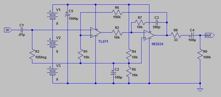
Indeed it does, and R2 halfs it to 50k. You could easily replace these resistors with 10M parts to solve that, at least as long as you choose a film part for C1. In addition to this I might use 10k instead of 100k for R4/R5 (somewhat lower noise) and replace the TL072 with OPA2134 for both lower noise and distortion. C2 and C3 might be more comfortable with a value of 100 uF or 220 uF.

Samuel[/quote]


Well, there are also a 22k and one 1k pot in paralell with R1, so I would must remove that to get the high Z at the input, isn´t?

C2 and C3, if want to get over 22uf, have to go to electrolytic type, the higher value I find in metalized poliester is 22uf. What would be better? 220uf electrolytic, or 22uf MKT for C2,C3?
I would like to put a rotary switch to control the gain level. Where I must put it?

What´s the mission of D1 and D2?
 
[quote author="lagoausente"]


Well, there are also a 22k and one 1k pot in paralell with R1, so I would must remove that to get the high Z at the input, isn´t?

C2 and C3, if want to get over 22uf, have to go to electrolytic type, the higher value I find in metalized poliester is 22uf. What would be better? 220uf electrolytic, or 22uf MKT for C2,C3?
I would like to put a rotary switch to control the gain level. Where I must put it?

What´s the mission of D1 and D2?[/quote]

yes, 22k and pot needs to go also.

yes, c2,c3 likely electrolytic.

To add gain, you need to change feedback topology, right now gain of 2. I would consider an instrumentation topology, using the two opamps.

?? If you wish to add gain, do you plan to not plug this into mic inputs? There is plenty of gain available at mic inputs.

If intended for line level interface there are several other considerations.

D1 and D2 probably to clamp transients related to phantom power at output.

JR
 
?? If you wish to add gain, do you plan to not plug this into mic inputs? There is plenty of gain available at mic inputs.

If intended for line level interface there are several other considerations.

I´ll go directly to the ADC line in. My preamp, is trafoless, so, don´t find reason why to go through it for colour.
 
I tried Simetrix Intro tool to draw again the schematic. So have removed those resistors, and the phantom supply, because I will use only battery.

If intended for line level interface there are several other considerations.

Yes, I want line output, to go directly to the ADC, and would want to add gain control, something like a rotary switch.
What changes must I add? Or maybe I have already had a mistake..From now, (edited), have realized I have forgoten R12 and C8 next to pin 1 on the original schem.
 
* R1 is at the wrong place (goes before the input cap)
* R1 and R2 should be 10M (mega) not 10m (mili)
* C2-C4 are electrolytic and should have a polarity mark (unless you are sure that you won't put them the worng way around without)
* To add a gain control convert X1 from a voltage follower to a noninverting gain stage with gain
* The output swing from a single 9 V cell may not be enough to drive your ADC to full scale

Samuel
 
Well, I leaped into adventure and put the variable resistor, and X1 as noninverting amp.
Anyway I asume that R4 and R5 values must be changed.
Has any sense the schem like is it now?
Believe me, I have reading about opamps today, but till now, haven´t find configurations with two opamps.
So, you´ll have to be a little patiente with me.
:?
 
I have reading about opamps today, but till now, haven´t find configurations with two opamps.
Divide and conquer: X1 is used as noninverting amplifier/voltage follower, X2 as inverting amplifier (in the original schematic).

The new version will not work. I realise that there is much more to say about it than I am willing to write so I've drawn a schematic: OPA2134_DI-Box_r1.pdf

Samuel
 
Thanks Samuel.
I made another try, asuming that will not work either.

Well, I would like to understand all these.

I was looking at the Green and Supergreen shems, trying to understand how they work, and hell, I don´t understand them. Specially why T1 and T2 have polarized Base-Emitter, since no voltage seems applied to the Base?
In the Supergreen for example: http://www.akustische-kunst.org/audio/supergreen/supergreen_schematic.pdf
I suppose that through T1 must be a current of 1.25 ma or so. To can have the same voltage after R15, then after R19. But don´t understand how the Base of T1 controls that current.
 
The transformerless preamps you mentioned are complex and the interaction of the opamps with the discrete frontend is subtle enough to probably make 99% of the people here not understanding it properly in all the details. I'd rather suggest trying to understand my DI-Box schematic first which is a just slightly extended implementation of basic opamp configurations. Beyond this you'll probably need to get a text book on electronic design such as www.artofelectronics.com.

Samuel
 
[quote author="Samuel Groner"]The transformerless preamps you mentioned are complex and the interaction of the opamps with the discrete frontend is subtle enough to probably make 99% of the people here not understanding it properly in all the details. I'd rather suggest trying to understand my DI-Box schematic first which is a just slightly extended implementation of basic opamp configurations. Beyond this you'll probably need to get a text book on electronic design such as www.artofelectronics.com.

Samuel[/quote]

:thumb:
 
Just thought I'd throw this in:

magicdi2.jpg


I built this one about 15 years ago, so it is kinda designed around the limitations of chips that were available at that time.
Nonetheless, it works well and is very clean and quiet. The fixed gain might be a minus.
I think it may be an exercise in frustration to build a good DI - WITH LINE-LEVEL OUTPUT - that runs on phantom - IMO. :grin:
 
I think it may be an exercise in frustration to build a good DI - WITH LINE-LEVEL OUTPUT - that runs on phantom - IMO. Very Happy

I haven´t asked for phamton at all.

Samuel have done another schem: http://www.sg-acoustics.ch/analogue_audio/miscellaneous/pdf/OPA2134_DI-Box_r1.pdf

I built this one about 15 years ago, so it is kinda designed around the limitations of chips that were available at that time

Are chips now a good way to do this type of preamp?
 
Bifet opamps are probably OK, I'd be careful about putting one opamp inside the feedback loop of another like magic posted, but if you pay attention to gain/phase shift you could experiment. I'd suggest keeping it more conventional until you get a few more solder joints under your belt.

JR
 
Q&D version: I simplified the design and converted it to run off a single 9v battery. This allows powering it with a typical pedal power supply or a battery, and switching the power on/off with the input jack as is done in pedals so you don't need a switch... Want more headroom? Feed it 12v or even 18v.

I changes a bunch of resistors to 10k because it's a common value and I have plenty of them around :grin: I deleted the input pulldown resistor since this is a direct box and you are not going to switch it... the input impedance is 1M, which is plenty for guitar and typical of the tube amps that they are usually plugged into. You can parallel R3 with a 10 to 47pF ceramic if RF becomes a problem but likely won't be needed at these gains in a metal box.

I'm not that familiar with the 2134 but if its a fet then it will be fine. The input impedance of a 5532 is too low for this application. The TL072 will be almost as quiet at these impedances. Put in a socket and try different chips.

Without some frequency shaping with an EQ, guitars will typically sound a little lifeless and thin when going direct.

I deleted a bunch of other components for simplicity's sake, and changed other minor things besides converting to a single 9v supply.

The "GND" point should be isolated from the chassis but Vee can be connected to chassis.

I have a box almost exactly like this that I've used for years.

guitar_di.gif
 
In an ideal world your PS will be centered by the 10k resistors but any significant load imbalance like asymmetrical output clamping might be problematic. A stretch I concede but I worry about such things. In one design I did to split a single supply for bipolar use, I used a simple pair of NPN and PNP transistors with their emitters tied to v/2 (your GND), both bases tied to the junction of a divider like your 2x 10ks, with the collectors tied to the appropriate rail, NPN collector +, PNP collector -. This way they only conduct when and as much as needed to balance the two supplies to no more than a diode drop imbalance. This window could be reduced by adding a diode or resistor bewteen the two bases. A small capacitor from base(s) to emitter(s) can slow it down if needed.

For longer battery life 100Ks instead of 10Ks as your "go to" R value would buy a little benefit, but the opamp nominal current will probably dominate consumption.

JR
 
Why to use a hard-to-get rev log potentiometer instead of making R4 adjustable (normal log potentiometer)?
 
[quote author="audiox"]Why to use a hard-to-get rev log potentiometer instead of making R4 adjustable (normal log potentiometer)?[/quote]

DC on it (input current) will cause noise when adjust gain.
 
Bifets have arbitrarily low input bias current and circuity looks like its cap coupled so there shouldn't be DC current or voltage across the pot in either location. One consideration of design is to fail gracefully. Since pots typically fail open, an open circuit would be less objectionable if the failure gain defaults to unity rather than WFO.

JR
 
Back
Top