What's this scope image telling me?

GroupDIY Audio Forum

Help Support GroupDIY Audio Forum:

This site may earn a commission from merchant affiliate links, including eBay, Amazon, and others.

jrmintz

Well-known member
Joined
Jun 4, 2004
Messages
998
Location
NY
Hi all,

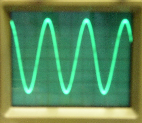
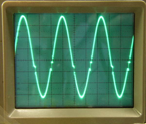
This is a scope image of an API 312 with 1k going in. I'm assuming the opamp is kablooey, but what's this image telling me? Is this crossover distortion? Also, does anyone know of a book or website with pictures of typical scope images and what they mean?

ScopeImage.JPG


Thanks
 
Looks like it. A little off center, but looks like the zero crossing point is funny.
What is your supply set at?
Which model API?
Check your input signal if you have not already, for the same thing.
Reduce the input voltage and see if it goes away.
What is your peak to peak input voltage?
 
can you expand the time so that we can more clearly see what that bad patch is doing? looks to me like the bad spot is reversing potential for/by a small amount... have you tried a different input wave to make sure it's not some weird anomoly of the scope/wave generator?
 
Are you feeding the signal into pins 2 and 1 or pins 2 and 3?

I had a similar problem, with much greater distortion when feeding 1 and 2, but feeding 2 and 3 was perfect....or did I get that backwards? I don't remember.

Also, what are you using to generate the wave? It could also be your function generator. What is the output voltage of the wave before you feed the preamp? Maybe the wave is too low in output.

Shane
 
Thanks guys. Here are some more pix. I'm using an Amber 3501 analyzer/generator. I hope I'm describing everything correctly.

Here's the scope reading the generator directly at -5 dBm, .4V (sorry for the fuzziness):
scope1.JPG


Here's the 312 at an expanded time base with the generator putting out 1K at -25 dBm and the analyzer reading -5.5 dBm input:
scope2.JPG


Same setup at 10K:
scope3.JPG


Same setup at 1K with 10dB of gain from the 312, analyzer seeing -15 dBm input:
scope4.JPG
[/url]

Shane,
It's an old card but I'm pretty sure it's hooked up correctly. It's been in use and sounding fine for several months.
 
hmm, it gets worse with frequency... interesting..

look at the upwards swing of the waves in the last pic.. hmm :?:

hows the power supply you are using?
 
What happens if you hook it to the alternate pin? i.e. swap 1 for 3 or vice versa. Your newer images are looking exactly like mine did until I switched pins.

Shane
 
Pins 1 and 2 are the + and - voltage rails, pin 3 is PSU common. They're straight and the power supply seems to be happily putting out +/- 18V. It was definitely the op amp. I took out the old one and put in sockets so I could try out a few different ones. I put in a 990C and it's fine.

Thanks for all your help. I'm still interested in knowing what the scope is saying, though.

:guinness: :sam: :guinness:
 
[quote author="jrmintz"]I'm still interested in knowing what the scope is saying, though.[/quote] My 0.02... I'm probably not going to say anything that would lead you to a direct conclusion but...
scope2.JPG -- looks rather like gross underbiasing

scope3.JPG -- makes me think poor high freq response = "bad capacitor"

scope4.JPG -- looks like your assessment of bad OA is correct and since you cannot open it up, you can't fix it anyway...but my understanding is that it would allow you to buy a new one from AP-"EYE" :grin:

HTH!
Charlie
 
[quote author="jrmintz"]I'm still interested in knowing what the scope is saying, though.
[/quote]
Just looking at the first and last waveforms...

Very specifically, where the trace goes to almost a vertical line, the rate of change of what's feeding it has increased significantly - as in what you get when you display a much higher frequency at the same timebase setting. You get this sort of display when, for whatever reason, there is instability - all of the compensation around the op-amp 'fails' for a fraction of the waveform, if you like. It's worth noting that with some op-amps that appear to have been compensated for a specific load, just the extra capacitance of a scope probe on the output seems to make them do this - but those amps are running on the verge of instability anyway. Svart's comment about the apparent reversal is spot-on - there are plenty of op-amps around that will do exactly this when their feedback loops are effectively broken by external circuit considerations, allowing the internal devices to saturate.
 
This kind of responce is exactly what I have come across in my API experiments. I've never tried a real 2520, just the clones I've built. The results are also borne out by simulation in Circuitmaker (waddever that's worth)

With all the 2520's I've done, as the 1kHz sine wave clips "normally" (flat top & bottom". Switch the signal gen up to 10kHz & the clipping looks awful, similar to the above pics. Back off the level slightly & it cleans up.

Are you measuring at the output of the opamp or the transformer? This can also change the waveform.

Changing the value of the feedback cap rolls off the top end but does not fix the distortion characteristics.

Peter
 
[quote author="SmG"]just the extra capacitance of a scope probe on the output seems to make them do this[/quote]
Perhaps switching the probe to X10 mode would help? The bandwidth of one of my preamps "magically" changes from 170 to 430kHz when I do that...

Best regards,

Mikkel C. Simonsen
 
jrmintz, it might be worth looking at Deane Jensen's AN-001 about stability in op-amps, which will tell you more about this kind of problem in a very readable way - he also suggests some possible solutions that may help when you come across this in other projects.

[quote author="peterc"]Are you measuring at the output of the opamp or the transformer? This can also change the waveform. [/quote]
Absolutely - there is more information about this on page 3 of the AN in the section about load isolation.
 
[quote author="mcs"][quote author="SmG"]just the extra capacitance of a scope probe on the output seems to make them do this[/quote]
Perhaps switching the probe to X10 mode would help? The bandwidth of one of my preamps "magically" changes from 170 to 430kHz when I do that...
[/quote]
Hehe! I'm glad it's not just me that this happens to!
 
Are you measuring at the output of the opamp or the transformer? This can also change the waveform.

These pictures are after the transformer, but the sweep looked the same with a probe before the transformer. I'll read that app note, thanks. It's a good thing they're self-contained op amps and the problem is easily fixed by just switching them out.

Thanks again.
 
[quote author="NewYorkDave"]The scope image is telling you

"Get... out! Get... out!"

:wink:[/quote]

:green: :green: :sam: :sam:
 
By all means, try switching your probe to X10 (and use the square-wave "cal" output on your scope to make sure it's properly compensated). But I doubt that a few extra pF of added capacitance from an X1 probe is going to make a real difference on the output of an amplifier that's designed as a line driver.

Is the transformer terminated in its rated load impedance, or is it just working into the high impedance of the analyzer input? Add the appropriate termination. Any change?

Replace the output transformer with a resistive load equal to the nominal primary impedance of the transformer. What do you see?
 

Latest posts

Back
Top