1073/1084 PCB Debug

GroupDIY Audio Forum

Help Support GroupDIY Audio Forum:

This site may earn a commission from merchant affiliate links, including eBay, Amazon, and others.

maxwall

Well-known member
Joined
Nov 17, 2004
Messages
1,134
I have always wanted to build a XX73 or XX84 classic but never felt right about the integrity of many boards and schematics circulating across the forums. It does'nt take long to sit down and find that most of them are riddled with error. I could'nt see putting good money and time into a risky layout that may not work as intended. So, here is a place where interested members can share info on DIY board artwork layouts that might be inconsistent with original manufacturers schematic diagrams. In Addition, there are some newer modern components available ( like inductors ) that will require board trace/pad modifications to fit these components on the boards properly. So feel free to post any schematic or board artwork that can eliminate the unintended errors in this project before etching a board for your XX73/84 DIY project.

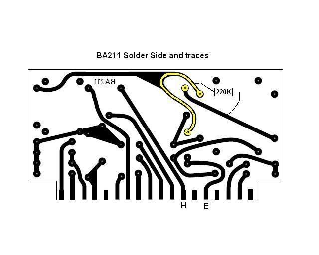
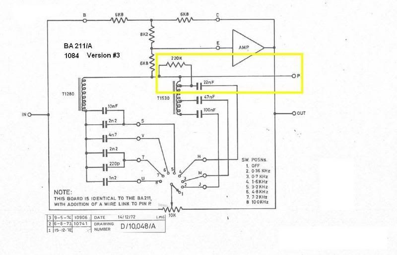
I'll start this thread with some inconsistencies (or board rev changes ) I have found on a DIY BA211 board found on a website we are all familiar with. It was posted by Chris Vallejo who mentioned that there were some issues , but never followed up on what they were. Ever since I stumbled across the artwork, I have yet to see any corrected information surface and have lost my patience waiting for the revised layouts on some of these possibly questionable boards.

So here is what I have found on this first XX73 board. Feel free to contribute to this or add another board and a diagram for debugging.
Corrective PCB artwork is also welcomed.

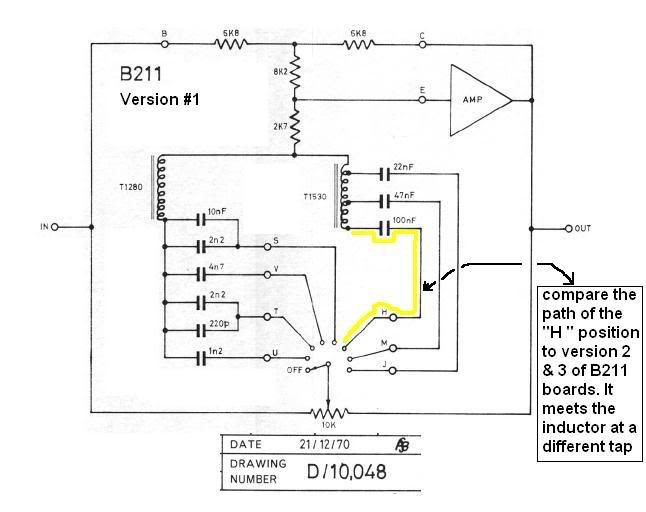
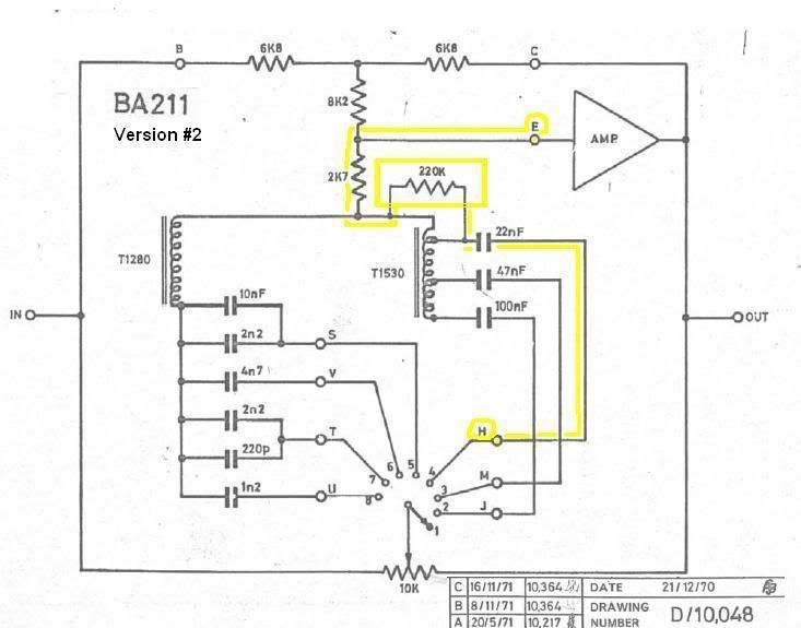
I have just discovered 3 different versions of the B211 board that need clarification.

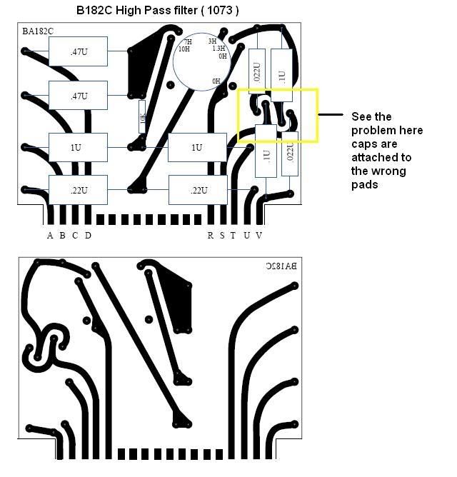
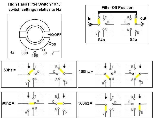
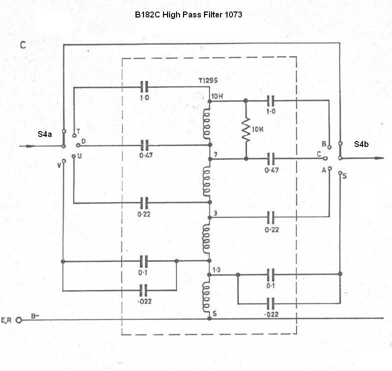
Just added B182C board with inductor T1295/VTB9043 , some minor corrections observed. I've added a switch position diagram that will help
folks understand the filter signal flow. This information can aid in discovering either bad artwork or misplaced component layouts.

Unfortunately, I do not have a 1073 module to compare with.
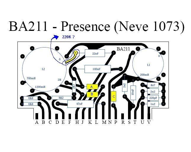

BA211.jpg

A = not used
B = not used
C = not used
BA211E.jpg


B211v1.jpg

BA211v2.jpg

BA211Av3.jpg


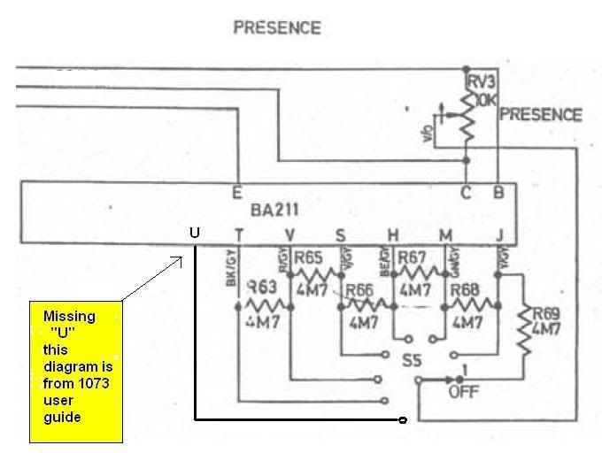
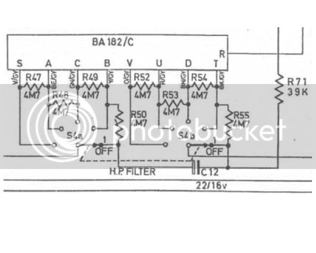
Here is an error I found right out of the Neve 1073/81 user guide published by AMS Neve - can you believe this. see below. If this were
to be installed in a 1084 then "U" is not used.

BA211sch2.jpg


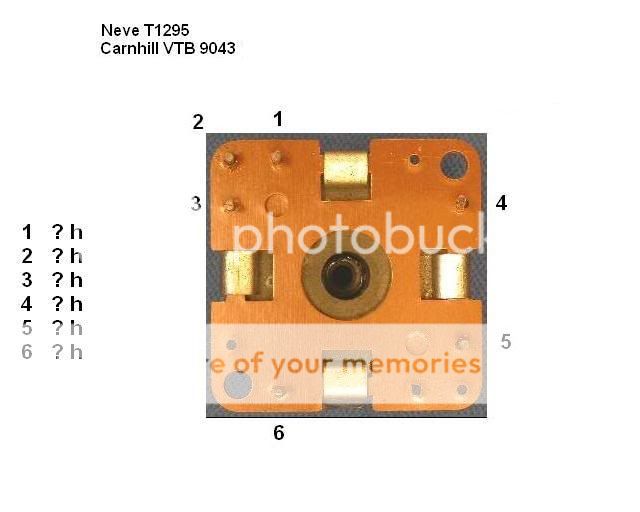
Here is B182C (1073 ) and T1295 inductor for general info and pinouts

B182Cart.jpg

182CSWSet.jpg

182Csch.jpg

182Csch2.jpg

T1295.jpg
 
hi maxwall,
glad to see you around here again.
i may be wrong, but i'm pretty sure that those are all 4M7 resistors (this is by referencing Chris V.'s layout on his website and also the schematic).
i believe that ALL the resistors from the B182C, B205 and B211 cards to the switches are all 4M7 resistors.
hope this helps, but please refer to the schem to double check.
regards,
grant
 
grant
not in the 1084 too but there an additional resistor (pad holes missing in this design) and according to schematics a wire between pad P and the commun Oh inductors trace.
btw it will better to use the 1073/84 help thread so everyone who need infos relative to thoses pres could find answers in a single thread....
audioforge
 
Yes I see it now from the original Neve schematic (fifth diagram BA211A) -easy, I failed to compare it with the schematic.

there are no resistor values listed for A,B,C - not used.

Audioforge is correct on this.

However if you were to use version 2 or 3 BA211 above there is a 220K resistor missing from the first component overlay diagram when compared to the Neve schematic. See rectanglar
yellow mark on the fourth diagram and compare it to the first diagram. Can you see the 220K resistor pad on the first diagram - not there. Looks like this was overlooked.

Does anyone agree with this ?

The 220K resistor should appear betweeen the 22nf cap and L1 (T1530) inductor originating at the H pad (first diagram).

Audioforge mentioned a wire between pad "P" and "0H" of Inductor L1 but I do not see this in the original BA211 schematic. Its found on the BA211/A version 3 schematic. A slight design change but I'm not sure why ?
Maybe for the 1084 version only.
 
you said "Maybe for the 1084 version only."
YES

To avoid confusion the pcbs layouts maxwall show in this thread are Chris Vallejo ones and NOT the ones i ve done for the actual pcbs groupbuy.
audioforge
 
Thanks for confirming that Audioforge

I see you have the DIY spirit - Sharing the info.
 
Good timing i think Maxwell , as we want to make sure this new round of boards are A-o.k. ,
thanks for the energy

I know it may sound less Neveish , but everytime a friend of mine sees the schematics ,
he winces and says there are better transistors than
the 2n3055 , anyone tried subs ?

regards Greg
 
The extra 10kHz mid position was used on the 1078.

Regarding the 2N3055, I tested a ST Micro years ago with strange results but it must have been a bad Chines copy as the ones I use today works just fine. Also seen that AMS-Neve also uses them.
There are loads of NOS Motorolas out there as they can't be used in productions anymore thanx to the RoHS thing :?
 
maxwall
I see you re doing the work i ve done 5 months ago.....
chris valleo design are a good base to do pcbs but they are not errors free (as you found on the b182c) and many footprints are wrong too..
the 9043 carnhill pic. notes you upload regarding the pinouts are wrong.
.3H ----- .1.3h ----- -------------- . 3h ---- .0h
----------------------------- and not
---------- --.0h ------- -------------------------.1.3h


and there s off course differences between 1073 and 1084 .
there should have been revisions for the boards.i ve seen pics of 1073 ba211 with the extra resistor 220k on.others without .and 1084 ba211 without the extra resistor.but who know if the 211 inside it ,was the original one ?
maybe Tekai have the knowledge about this question.....
audioforge
 
Audioforge,

Yes I believe your observations to be accurate. I'm glad Tekay is around too. I'm sure there are people viewing this thread with more knowledge to share than I have , hopefully we can see them get involved here and there as needed.

Please understand that my mission here is to clear up a lot of innacuracies not found in most other threads of this nature. I not sure why I'm the guy who has to bring all of this to the forefront, but to my knowledge no one else has made the effort to get the facts out. I know I'm not alone since I've been on the forum for some years now and have discussed this issue with many respected and professionally skilled forum members as well as newbies. There is a consensus about information exchanged here, it weighs heavily on accuracy.

Well , In the spirit of DIY ( whatever is left of it today) a true and accurate effort is really needed here for folks who wish to keep the project of DIY real as opposed to being amateur. To do so, it takes some dedication. nuff said

Unfortunately I'm working with available information that is obviously not accurate. So you understand what most DIY members have to go thru
when building something posted on this forum. I think all can relate to that , I'm sure. As I mentioned earlier, I do not have an original 1073
module to work from so I'm contributing my best efforts given the
circumstances.

Yes, the footprints from C.Vallejo's (CV) boards have innaccurate traces or footprints but I think they are mostly functional. I will try to revise and repost artwork and info as it becomes available to me.

In your last message you indicated the inductor I posted is labeled incorrectly and it looks like you tried to provide the corrected info , but I'm having trouble understanding your explanation , maybe you can post a simple drawing which shows the pins and values of this inductor. To my knowledge, Carnhill does not provide a data sheet for this inductor so I used my ohm meter to try and figure it out, since I own one of these VTB9043's parts.

Audioforge, thanks in advance for any help you can provide.
 
maxwall
Here the corrected 9043 pinout.
Look at your pic.and rotate clockwise
upper left is ground ----- on the right 0h then 1.3h a bit lower 3h
right down pin 7h left down pin 10h.
Carnhill do not provide thoses infos (i ve asked with no success when i done the inductors groupbuy).I ve measured the inductors and gave a wire color guide to the g.buy members.I will post it in the 1073/84 project help thread so people who bought their inductors from Colin (audiomaintenance) could easily plug their inductors in the pcbs.
I m confident about my pcbs. The main problem will be the wiring as you note(as i do too) that s schematics are confuses....(especially the ams ones..did i said .paranoia.?....)
but nothing unfeasible with efforts, a good oscillo and benchmark ( i have) and some maths......
Of course the more accurate infos we ll have (before building the project)the easier it will be............
I was feeling a bit alone with this project. not anymore. thank you man.
audioforge
 
[quote author="audioforge"]grant
not in the 1084 too but there an additional resistor (pad holes missing in this design) and according to schematics a wire between pad P and the commun Oh inductors trace.
btw it will better to use the 1073/84 help thread so everyone who need infos relative to thoses pres could find answers in a single thread....
audioforge[/quote]

Audioforge,

The pad is NOT missing...in the original the resistor is soldered at the back of the PCB.I'll try to open a real one when I get a chance but this is what I recollect.

Also maxwall,

whose boards are those in which you're indicating the mistakes?
 
codered
you said" whose boards are those in which you're indicating the mistakes?"
the answer was upper in the thread.here it again:
To avoid confusion the pcbs layouts maxwall show in this thread are Chris Vallejo ones and NOT the ones i ve done for the actual pcbs groupbuy.

codered if you have access to yeal 73/84 rack could you take hight resolution pics?
i never see, on 1084 pics i ve ,b211 with a 220k resistors solder on the cooper layer side.... what annoy me more is the link between pad P and the commun between the 2 inductors.so if tou have access to a real one, it will be great if you could check that point.
btw do you have a schem or a pic of the board after the original output edgeconnector? it s that one you asked from me i suppose.....
i could maybe help you .
audioforge
 
Codered

thanks for dropping by this thread. I see you have some useful information as you have demonstrated. I hope we can have you here to contribute to the success of this whole effort of degugging or de-mystifying some of these old Neve board layouts. I think you will agree that information from one person to the next can get skewed affecting the final outcome. So now you can see why I'm trying to finally tie it all together here on this thread.

Unless you own on of these modules one can only speculate rev changes and diffferences that exist between schematics and actual units. But , the last thing I want to do is speculate a design for a project so Its going to take a collaboration of knowledgable DIY people to bring it to where it should be. This way were not wasting time building crappy audio boxes on this forum.
 
Doesn't Dan Alexander or someone have a few of these original boards sitting around? All you need to do is photograph them and figure things out against the docs. Max, you're in SF, give Dan a call. He might have boards you can buy. Or else, find a studio that has functioning units (there are several in SF area) and pay them $25 or whatever to walk in, open the module case and take some snaps. A friendly studio owner who's not too busy would probably let you do it for free. Even if it costs $50, like to rent his neve room for 30 minutes, just do it. Saves you lots of hair pulling.

And aren't there enough photos of original boards out there already in the public domain? Why work from drawings of boards, when you can work from photos?

That way you can confirm at least one version of the original boards. Then the rest is simply connecting the dots, confirming the module board to board wiring against the known boards. It's the systematic way to approach it.
 
First and foremost this is DIY and I have to keep this project as cheap as possible. because we all know that the module I intend to build is gonna cost some dough in parts alone. Dough that is not easy for me to come by since I'm self employed. As a note most of the expensive parts are out of the UK and the exchange rate is 2 to 1 with USD. Not the best time to build Neve preamps. As all Carnhill stuff is coming from UK. and Don't forget you have to add in all the nice Elma switches too.

Public domain Boards floating around on the internet are not going to be my first choice for obvious reasons.

I could call Dan but he's a busnessman and I don't want to waste his time because he will need to profit from it somehow. I do have a studio friend who knows Dan maybe I'll contact him.

If I go to a studio in SF their not likely going to let me tear their modules open to get the needed info. Maybe If I had a connection at a studio this would be a different story. but I dont have the connection for this.

Your in the bay area and your a DIY member, have you any connections that may help ?

IF not ....

I'm back wear I started.

Fortunately , the least of my worries is connecting dots.

Although I have to thankyou for dropping in on this thread and if you happen to have access to boards I and my digital camera will gladly meet with you.
 
Where , and How much per day ?

Most of these rental places put tamper resistant labels to prevent
the opening up of equipment. Then they ding you if they find the label
was removed or disturbed.
 
Back
Top