Comments on an automotive circuit...

GroupDIY Audio Forum

Help Support GroupDIY Audio Forum:

This site may earn a commission from merchant affiliate links, including eBay, Amazon, and others.

SSLtech

Well-known member
Joined
Jun 3, 2004
Messages
5,447
Location
Florida (Previously UK)
I'm trying to come up with a comprehensive dome-light delay & fade circuit for adding into a couple of older cars.

I've seen a couple of circuits but nothing with everything that I'm looking for yet...

So I adapted the one that had MOST of what I was looking for:
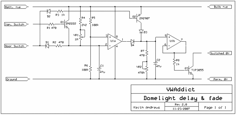
Domelight-2.gif


There are two stages, U1a does the actual delay, which cancels when the ignition key is turned to the 'run' position. (I hate the wife's Volvo factory circuit, which keeps the light on even when you're trying to drive away!) D2/R3/TR2/D3 is the bit which I added on, trying to get the light to still come on if a door is opened with the engine running, but with NO delay when it's reclosed, unless of course the engine is switched off.

U1B is a buffer which drives the simple TR3 switch for a gentle 'fade-off'.

I can't say that I'm in love with the R8/TR3 fadeout circuit, because it depends on hfe, as well as the bulb's load resistance, and that makes a super-smooth fadeout hard to predict... but I don't want the circuit to be much more complicated.

Anything else anyone can suggest?

TIA,

Keith
 
Short of something significantly more elaborate, I'd load the base-emitter junction of the 3055 with a small-signal transistor connected as a predistortion diode. You get some temperature compensation and a more linear transfer function.

EDIT: Actually, if the opamp is of the ground-sensing variety (358/324 style), a small R in the emitter of the 3055 could provide a current shunt and the inverting input of the opamp connected to it. Then scale down the ramp signal appropriately that is fed to the non-inverting input. You could probably get away with just a few tenths of a volt.

I'd consider a MOSFET in that case, so there are no issues with opamp drive current. Be sure to put a RF snubber R in series with the gate.

What's the warm resistance of the bulb?
 
Just making a little drive by design suggestion.

Perhaps drive the base of Q3 from a voltage divider that would go up to say 1V full on if base wasn't connected. The threshold and delay may vary with temps but like this isn't rocket science.

JR

PS: You could probably do the whole thing with less battery draw using something clever in 4000 series CMOS.. I used to do trick stuff with 4007, but for simple logic, maybe just use logic?
 
make shure that you protect your circuit from high voltage pulses.
positive and negative. they can up to +-100V.
i working for a automotive electronic supplier and we do test on the electronic. we make pulses depend on the customer (FORD,GM,VW,AUDIO,....) and they have high voltages. the hardest is the load dump. they goes up to +100V for some ms with an RI=10 OHM.
thats power. we use transorb diodes to protect the circuit.
 
Keith maybe use a mosfet (like Brad posted)after the first opamps diode logic.
Diodes junction then a series resistor(like R8) then use a film cap cap from gate to ground to set delay off with a 10meg(what ever values work with the film) bleeder gate to ground. Gets rid of R7 C2 and VR2 1/2 opamp

Use a n channel low Rdson power mosfet instead of the BJT. If you try this you might want offset the opamp more to +12 then center.

Is this going to be connected all the time being a dome light.

A chart of inputs and wanted outputs

Plus you need to get clean power like posted by maxheadroom.
 
I looked a bit more at the schematic.

If the door is open(when the door is closed there is a good path to ground via R2 and D1) and the Ign switch turned to start and the battery voltage dropping due to starting what kind of pulse might be generated at pin 2 of the opamp?

Just thinking of protecting the input section maybe a 1k from the top of the C1 node to the input of the opamp?

I do like this idea for cars that don't have dome light control like this.
 
+100V with Ri=10R? We have an automotive customer that specifies +100V with Ri=0.5R. Ouch!!! Automotive tranzorb, Vishay SM8A27 works for us but it barely passes that test. But remember that the tranzorb will clamp at about 45 volts with a load dump current of 60 or 80 amps, so any IC connected to this rail needs that kind of load dump capability. Normally we run it into an automotive grade voltage regulator (TLE4267 or TLE4270 are nice) and run everything on 5V. We try avoiding IC's right to Vbatt or Vkey. Remember you get reversed battery all the time, too. You can use a series diode, but I usually use a backwards P-channel FET. It takes four parts (two resistors, a zener diode, and a big P-channel FET like the NTD20P06 or something like that.

Most lighting control computers (often a BCM - body control module) use a processor to PWM the lamp. In the analogue world, you can take the analogue voltage output, compare to a triangle wave (from a low-power 555 timer, and a comparator (LM2903), and a MOSFET. That makes for a (relatively) linear control law once the bulb is at temperature. So the fade-in should be repeatable, but different than the fade-out. I would also look at an intelligent (protected) MOSFET - IPS031, for example, or maybe a NID5003. They are more rugged. There should not be much lamp inductance so you shouldn't need a flyback diode. A 2200 pF, 100V capacitor on each I/O line to ground would also be wise to prevent interference.

-Dale
 
Back
Top