CAD drawing of ribbon capsule made with off-the-shelf stuff

GroupDIY Audio Forum

Help Support GroupDIY Audio Forum:

This site may earn a commission from merchant affiliate links, including eBay, Amazon, and others.

Consul

Well-known member
Joined
Jun 3, 2004
Messages
1,653
Location
Port Huron, Michigan, USA
Well, that was the idea, anyway, when I drew this in engineering graphics class (aka CAD class):


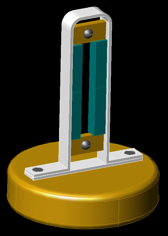
The idea is to use modified angle brackets (that means bent at the top) plus a base bracket (at the bottom) to form a closed magnetic circuit. The ribbon clamps are an insulative material, which can be picked from many choices. One half of each clamp would be glued to the brackets, then the other would screw down, as can be seen in the drawing. The magnets are 1/4" x 1/4" x 1" neodymium jobbies that I already have in possession. As this is designed, it would accommodate a ribbon two inches long. The base is three inches in diameter to give a size reference.

Any thoughts? I just thought I'd run this by, and if it turns out to be a bad idea, I still get the class credit for it. :wink: Thanks!
 
Hey Consul,

Nice drawing.
As for the practical implementation, as they are now, I think it will be hard to make the braket sides absolutely parallel and it does not have needed rigidity.
Also, it will be hell of work to install the ribbon into this thingie more or less presisely.

Keep refining :thumb:
 
Thanks for the reply!

Believe me, the brackets I have in mind will be more than rigid enough for this. In fact, my main concern is figuring out a way to bend them at the top that won't break my fingers or equipment. The parallel problem obviously will need more care, but for a one-off, I'll bet I can brute-force the whole thing to fit together. Fitting the ribbon will be a pain, but when won't it be?

The idea here is no special tools, off-the-shelf parts, and common materials, while adhering to as many of the design principles of ribbons as possible (closed magnetic loop, etc.).
 
[quote author="Consul"]

... adhering to as many of the design principles of ribbons as possible (closed magnetic loop, etc.).[/quote]

Often, breaking textbook design principles is the way of making progress :wink: .
 
Well, betcha by golly garsh, Marik, if'n I didn't know better, I'd say you was teasin' me with somethin' you know that I don't.

:wink: :green:

Naw, it's cool, and I understand what you're saying. I imagine I'll go through a few iterations before I'm really happy with the result. Thank you for your input, I appreciate it.
 
...My old Shure ribbon looks like two bars of metal in which the center has been scalloped out by a very large router bit, almost looks like the conical tip of an oversized drillbit.

Ribbon.JPG


It is clamped in on the side of these large bars and affixed to the mic body.
 
Neodymium may not need a closed circuit like Alnico did.

That avoids a nasty top bend, assuming your ribbon mounts are up to the task of bracing two strong magnets apart.

My drafting background asks:

What are the red dots? Need a new eraser-crumb brush?

Why are verticals not vertical? Doncha know how to tune a T-square?

My instructor would have taken off points, and told me it had to be clean for the almighty Client.

Worse here, because slanty ink might be crooked blueprinting, but the digital image "Jaggy" calls attention to what ought to an "exact" drawing.
 
Hehe, well, I have an answer for everything!

The red dots are an artifact of hiding the layers holding the dimensioning information. I don't know why AutoCAD does that, and it annoys me as well.

As for all the other questions, well, let's just say 3D solid modeling is not really AutoCAD's first area of expertise. It's what I had handy, though, so I used it. And I'm acing this class, I'll have you know. :razz: :wink:

Eliminating the closed magnetic loop would really simplify the construction, to be sure.
 
I'm not so sure about 3DSMax, actually. You see, the funny thing is, I love AutoCAD as much as I do because it's so manual: I can type in whatever command I want, I can type in the lengths and angles I want lines at (very big deal for me), and I can type in exactly how much and in what direction to move an object (also a big deal to me). I got frustrated with Solidworks, which everyone else in the class prefers for solid modeling, because it had none of these features. When I draw a line or move an object, I want to tell the dang thing exactly how long or how far, and none of this "freeform draw now and dimension later" crap. The console is what makes AutoCAD so usable to me.

I put that mic capsule model together, from scratch starting with nothing but an idea in my head, in two hours. Most of that time was spent stopping and figuring out what I need to draw next, and that includes redrawing the bracket because I messed up a calculation the first time around, as well as completely dimensioning every part. Two hours in Solidworks, and I figured out how to draw a line of unknown length.
 
All of the manual object creation tools are available in MAX as far as I can tell.

I take it you are using the Autodesk CAD. From my experience it is a scaled down version of 3dsMAX.

I felt like I had a limb or two cut off trying to use it for modeling.
 
Yeah, 3D is not AutoCAD's strong suit, but I got pretty good at it. I did nearly all of my assignments using solid modeling.

Now if you want standard 2D drafting, AutoCAD really shines, I think. I did a good amount of that, too, and was amazed at how fast I could do really complex drawings.
 
Yeah, i totally agree with you about the manual aspect of autocad. So much better to be able in input numbers instead of clicking icons and dropping shite. You can start drawing so fast when you get it down.
 

Latest posts

Back
Top