GT Speaker Emulator - not working

GroupDIY Audio Forum

Help Support GroupDIY Audio Forum:

This site may earn a commission from merchant affiliate links, including eBay, Amazon, and others.

volta

Well-known member
Joined
Dec 10, 2004
Messages
118
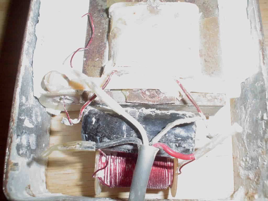
I opened this thing up the other day and found a
box with some drywall looking stuff in it.
Since it's the first link in the chain I had to see
what was in it so I carefully chipped away at it to
reveal three inductors and a cap.The cap was
bubbled up and leaking so that is safe to say it's fried.
The inductors all read about 1 ohm.
Never seen an inductor read that low.
Is this normal or should I assume they are fried as well?
GT-SE.jpg

GT-SE2.jpg

Patentstorm has a link about Q inductor with multiple metallization levels.
It states "In a preferred embodiment of the novel inductor according to
the invention, the stacks are connected in parallel having the first
terminal at the interconnected first ends of the strips and having the second terminal at the interconnected second ends of the strips.
The DC resistance of such an inductor is extremely low (typically <<1 ohm) and its inductance is typical in the range of 1 nH."
Could this maybe be the case with these inductors?
http://www.patentstorm.us/patents/6124624-description.html
 
If that is the groove tubes one , the marshall rackmount was licencsed
from them if you can find that schemo

i love to see it as well , or the Palmer which got stopped for a while
because it was apparently too close to the patent .

good luck , let us know
 
This is the older Groove Tubes speaker emulator they
later came out with the SE2.I think they had some
issues with this older model.The chips on the top
pcb are NE5532 and TL084 that go to the e.q. pots.
The lower pcb is the gain stage where I think the problem
may be.Still need to check everything but I was curious about the inductors.
 
I'm still searching for the " perfect " load box
but you wonder why they didn't make the eq passive
like a gtr amp .

I have a small palmer D.I. , not bad but you never get the room that way , still apparently allot of the satriani was done that way .

Anyone used the Sequious ? schematics for palmer G.T. or Marshall ?

thanks again for the pix though , inductor looks simple
 
Yes the smaller inductors look simple but the
big transformer looking thing has only two leads
so I assume it is an inductor as well.
Given they all read around the same dc resistance I'm perplexed.Any thoughts?
 
> Never seen an inductor read that low.
Is this normal or should I assume they are fried as well?


This is a "fake speaker", right?

Tube amps have high output impedance. Their in-use frequency response is dominated by load impedance. Guitar speakers have big impedance lumps. Around 8 ohms at 400Hz, rising above 1KHz, and with a big bump near 100Hz bass-resonance.

A tube gitar amp loaded with a simple resistor will not give the expected "sound".

The electro-magnetic parameters may be approximated with a resistor, a choke for top-rise, and an L-C tank for bass resonance.

The chokes are a lot like speaker crossover chokes. DC resistance must be much lower than speaker resistance. 1 ohm is quite likely.

The bubbled cap could be a bad reaction with the plaster. But it will also happen when BIG bass is thumped into the system, especially if the designer did not appreciate how large the tank current can get. I suspect that commodity bi-polar electrolytics can NOT swallow the full output of a large gitar amp with a boom-happy player. IMHO, it calls for a film-cap the size of a can of Fosters lager.

> wonder why they didn't make the eq passive like a gtr amp.

This "EQ" corrects the difference between speaker electrical input and speaker acoustic output. Since there are all kindsa speakers, it needs some diddle-knobs. It could be done passive, and maybe it is. The chips might support the Balanced Output and other pro-audio interface frills (cheaper than a dumb transformer). Or they may wrap around the EQ.... what's the difference?
 
Thanks PRR,I have a way better understanding of the circuit now.
I'll replace the cap and look down the signal chain for the problem.
Not sure I can fit a cap the size of a Foster's can in there. :guinness:
 
[quote author="12afael"]impulse based speaker simulation is the best for me.[/quote]
That's what I'm wondering as well, how 'relevant' is the hard way now there's more or less convincing DSP...
It's of course comparing different things; the GT is to add to a sweating amp, but still...

W.r.t. Marshall schematics, I had the SE100 (?) schematics uploaded but might have removed these recently, should check. Just let me know if someone wants them.
 
Well it's still like hearing reverb added to a gtr where it doesn't sound like a room
but sounds like a room coming from a speaker box
[ small and directional , not like a room coming from around you or
More & more these days we do orchestral recordings
with electric intruments or pop combo bands and are forced to more
close micing of the orchestra [ for self preservation and to get a useable
signal without too much pop band in it ] and the obvious thing is that
although you can get close it just is not the same when you add reverb
to the close mics instead of the sound of " micing the room " when you
have mics pulled back farther on 60 muscians in a large room .

But for the close mic 57 on gtr fans the D.I. recording & simulators can
seem close , another paralell though is that you can hear a well done
simulator and think it o.k. , but to play it in real time still , is not like a
loud almost out of control amp , live in a microphonic senstive reactive
way , sometimes more like an overdrive " box " or preamp only where
the results are acceptable the the feel not always satisfiying .

btw i thought some of the Ulrich Roth playing [ not recording ] was some
of the most orchestral compatable [ style wise ] i've heard .

So simulators there yet ? not quite i think , imagine those rap recordings
where nothing sounds mic'd !

enough [ probably too much ] for now regards Greg
 
Looking again for schematics , Bump

Kind of like expecting a synth to sound like an orchestra
[ the modeling / sampling gets closer but ......]

another fine way to waste time  [ lately I've been blending two sources , whether
one mic , one direct / two mics and sometimes two direct , when I have the time to work it ]
 
Hi,

Looks like the schematics popped up here (SE-II)

http://forum.metropoulos.net/viewtopic.php?t=38308

but both pdf-files seem not OK,..

Does anyone happen to have downloaded 'healthy versions' back then ?

Thanks!
 
okgb said:
Well it's still like hearing reverb added to a gtr  where it doesn't sound like a room
but sounds  like a room coming from a speaker box
[ small and directional  , not like a room coming from around you
Simulators, whether analog, digital or impulse-based, give a one-dimensional simulation at a time, they can't approach the 3D soundwave created by a simple guitar cab, that multiple mics can pick up. It would be quite possible to use as many simulators as needed to replace a system with closed and distant mics. That works relatively well, because the mics don't move relative to the source.
This not the case with vocal mic simulators, where the important proximity effects variations are not handled properly.
Indeed, analog simulators (and some digital) do not offer the infinite variations of the impulse-based types.
 
groove tubes is part of Fender now....

Fender does not express any concern over their amp and pro audio stuff and seems all concerned with the tubes. You may consider asking fender service department and see if they have anything. They have been kind in the past and sent me vipre and brick schematics.
 
pucho812 said:
groove tubes is part of Fender now....

Fender does not express any concern over their amp and pro audio stuff and seems all concerned with the tubes. You may consider asking fender service department and see if they have anything. They have been kind in the past and sent me vipre and brick schematics.

Thanks, yes, the friendly people @ Fender sent me the schematic for the SE II  (I guess it's best to check them as well if in need for this one, they responded quickly and didn't request a proof of ownership).

No idea if the alike sections (SE original vs SE II) have been tweaked w.r.t. component values.
Bit puzzling w.r.t. component values of the reactive load, one would assume the patent giving misleading info and the real schematic the correct ones... it's the other way around: 
R & L series:  50 Ohms  (?!) + 1 mH, then the resonance C || L: 200 uF || 16 mH (OK), but then in addition a 100 nF in series with this whole lot... 

But FWIW, there are some more (and more obvious) errors in the schematic, like +/- input swapped opamps etc, but with the actual unit next to the schematic all will be clear.
 
abbey road d enfer said:
Simulators, whether analog, digital or impulse-based, give a one-dimensional simulation at a time, they can't approach the 3D soundwave created by a simple guitar cab, that multiple mics can pick up. It would be quite possible to use as many simulators as needed to replace a system with closed and distant mics. That works relatively well, because the mics don't move relative to the source.

I see, using multiple speaker emulating paths if I understand it. Although elaborate, it's a nice idea, wondering if people have been using this in the past (before software became good at it).

Bye
 
my next speaker emulator will provably have this http://amtelectronics.com/new/amt-pangaea-cp-16-module/
 

Latest posts

Back
Top