On-stage buffer for acoustic guitars

GroupDIY Audio Forum

Help Support GroupDIY Audio Forum:

This site may earn a commission from merchant affiliate links, including eBay, Amazon, and others.
G

Guest

Guest
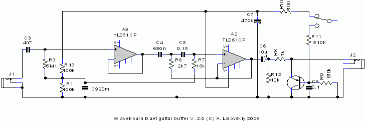
Please criticize, I need something urgently tonight where people will plug in pickups of acoustic guitars. High impedance in, 80 Hz HPF, foot switch with mute. Have no pickup to try...

Do you see errors?

Duet.gif
 
Personally I would simplify if things need to be fast--skip the discrete buffer, use one opamp as follower instead and the second opamp for a 2nd or 3rd order HP which should be enough anti-rumble for most applications. Less parts, less power consumption, less noise, less distortion, less trouble--OK, less fun...

I think Wavebourn has gotten creative on us with his rail splitter. The DC Q-point at the collector of Q2, through R13 and filtered by C9, set the Q-point/center bias of A1 and A2.
Indeed, but doesn't this change the very-low-frequency response of the filter..?

Are you sure it even needs an "Off" switch?
He want's a mute.

Samuel
 
[quote author="mediatechnology"]
Just had a quick look, but I guess C9 wants the company of two resistors across the supply ?

Peter - I think Wavebourn has gotten creative on us with his rail splitter. The DC Q-point at the collector of Q2, through R13 and filtered by C9, set the Q-point/center bias of A1 and A2. No wasted watts - very clever. :thumb:
[/quote]
Ah right, the quick look assumed AC-coupling of the preceeding stage... but it's not. :oops:
I guess the idea is nicer than the amount of actually saved power...
 
Thanks people!!!

Ok, R9 has to be bigger because of R4, let it be 20 uF, and 20K instead of 100.
Input resistor: is 5M1 Ok?

Option 2 (more fun): the same repeaters as on input instead of opamps.

Option 3 (faster) , opamps only, 3'rd order filter.

Thank you for feedback! I'll go with option3, 5M1 input. :thumb:
 
[quote author="mediatechnology"]
Quote:
I think Wavebourn has gotten creative on us with his rail splitter. The DC Q-point at the collector of Q2, through R13 and filtered by C9, set the Q-point/center bias of A1 and A2.

Indeed, but doesn't this change the very-low-frequency response of the filter..?

C9 probably should be larger. Didn't even see the "1" above the dot. I was thinking something bigger.
[/quote]

Yes, I saw that!

For a mute couldn't one use a shunt switch on the right-hand side of R8 and skip the transistor?

I have SPDT switches only; want to avoid thumps... The concern about transistor is, how big is signal from piezo pickups?
 
Wait--the bias trick with C9 works only if R3 is referenced to half the supply and not ground. :!:

As shown we don't get negative swing--and once you have the divider for R3 you can use it for the rest as well.

Samuel
 
[quote author="Samuel Groner"]Wait--the bias trick with C9 works only if R3 is referenced to half the supply and not ground. :!:

As shown we don't get negative swing--and once you have the divider for R3 you can use it for the rest as well.

Samuel[/quote]

According to datasheet for JFET there should be 3-7V, quite workable. I was thinking of a trimpot, though.
 
[quote author="Samuel Groner"]OK, was thinking bipolar. With the opamp-input you need it though.

Samuel[/quote]

Absolutely agree. There will be a voltage divider of couple say 100K resistors.
 
[quote author="mediatechnology"]Much simpler.

Would you want to add some out-of-band HF rolloff at the input? A simple RC?[/quote]

Do I need that? There will be about 100 feet of cable at the output.

May be couple of diodes to rails on input?
 
A 1k series at the input and a 10 pF to ground might help for overload and RFI protection.

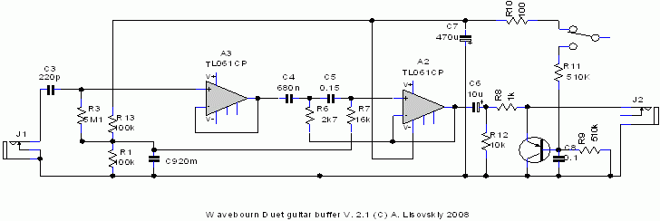
Not sure if I would use a 220 pF input coupling cap--that sounds very high impedance-ish which is asking for trouble.

If you want a 3rd order you might use the calculator here:
www.beis.de/Elektronik/Filter/Act3PoleLP.html

Just LP, but I think you can swap Cs and Rs to get a HP (or am I wrong here..?).

Samuel
 
With 061 @ input you'll get hisssssssssssssssss. If you look at professional guitar circuits with 06x, you'll see they regularly use pre and de-emphasis around filters to reduce s/n ratio. 2caps/4resistors is usually cheaper than other brand opamps.

Therefore; I'd use a cheap 2N3819 s-follower @ input stage with say 10Meg gate resistor shunted to ground with 33pf and conneced to pickup DC-style (with optional 68k serial resistor for "fender 12ax7 vibe" plus a FERRITE BEAD for no-radio-thank-you), and an affordable lf351 as the opamp (iirc it sucks 1,4mA ICE-LEMON juice !!). If lowpower is a requirement, I'd look into (also affordable and adorable) mc33171 (he's a MCeee, mann!!!). Lower noise than 061 in any case.


Now ... if I remember well, you were the one bitchin' bout doin' others homework in my thread?

Shame on you.
 
Shame on you, tv! I did my homework asking to criticize!

I use what I have in my bin because I need it urgently. 061 may be enuff for piezo pickups and a battery. In case of hiss I'll make version 2 (see above)

Thanks anyway!


By the way gentlemen, how much capacitance have 4007?

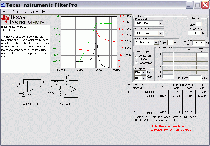
Samuel, I used TI calculator. 220 pf for 5m1 is what the doctor prescribed.
 
[quote author="mediatechnology"]
By the way gentlemen, how much capacitance have 4007?

I think I would worry about leakage too.[/quote]

Ok, I'll use something smaller since no capacitance is needed.
 

Latest posts

Back
Top