D-AOC PCBs - the building and help Thread

GroupDIY Audio Forum

Help Support GroupDIY Audio Forum:

This site may earn a commission from merchant affiliate links, including eBay, Amazon, and others.
Thanks for the info about the burned resistors.  I'll be curious if anyone else has had these getting hot or burning out.


dagoose said:
...i paralled 2x 100k to get 50k.

Does that work?  I would think you'd still get 100k.
 
i bought some nylon screws,washers and nuts to isolate the voltage regulators in my project. will these melt if they get to hot?  will the lm350 get to hot for them?
 
seavote said:
i bought some nylon screws,washers and nuts to isolate the voltage regulators in my project. will these melt if they get to hot?  will the lm350 get to hot for them?

Hi,
Your nylon screws should be fine but you could use some termaphase,silicon for the reg.

 
hoping to get some trouble shooting help. i hooked up the 6.3V and 24VPSU supply. i adjusted trimmer to get 6.3V with tubes installed. then hooked up the 220V from the tranny to the D-aoc PCB. the fuse blew when i turned it on. i checked for anything grounding out,solder bridges up to the voltage regulator but found nothing. next i pulled the voltage regulator from the circuit thinking(maybe incorrectly) that it would isolate the circuit up to that part.  installed another fuse and tried again. no luck. first i'd like to establish whether im using the correct fuse.
in a previous thread someone stated they were using a slow blow 250ma fuse at 220  so a 500ma would be good for110V. i asked for this at the electronics store. the salesman gave me 500ma fuse that has some 220V and 120V ratings that i dont understand.they are as follows:IR 35A  250V
                                                                          IR 10KA 120V
     is this the voltage drop thru the fuse itself? and how do i use that info? i believe it might be important to know im using an ac inlet with a fuse for both the hot and nuetral. does this change the values i should be using? i put 500ma in both.
     the hot is in series with the on/off switch and i have a 120V indicator lamp (3 watts i believe?) hooked up in series befor the power transformer.
      with the fuse for the hot not installed i turned on the comp and bridged the hot fuse with my meter to see how much current was being drawn. this blew the fuse in the nuetral side. i never checked the voltage coming from the 220V leg of the transformer but i'll need to get some more fuses befor i try that.
assuming the fuse i've been using is correct. where (how)do i test next? thanks for any help and ideas.
                    chris


Hi,
check the power tx´s primary. Are there two winding with 110V each? Maybe they are connected wrong.
Here´s a little helper:

How_to_connect_Power_Transformers.gif

regards
Bernd
 
thanks for the reply. i understand how to hook up the transformers and "knew" that i hooked them up correctly. but i checked  that yesterday anyway. its ok. correct me if im wrong but my thinking was that if i got the correct voltages from the 6.3V and 24V legs of the PSU the tranny hook up must be correct. is that untrue?
 
yes, since your heater voltage and the 24V work you have connected the transformer correct.
without the regulator you are isolated from the circuit if D5 and the 3 zener diodes are wired the correct way (I start looking for that).

would need to look in mine, but I think I mostly use a 500mA fuse (230V).
 
thanks silent. checked diode direction.all good. checked for open diodes(in that part of PSU, )none.tested in circuit. i did find that the primary wires to the left side output transformer were reversed. would this be the cause of the blown fuse? i also found the middle pin of the lm350 is grounding out. strangly it is not connecting to ground thru the IC itself. it's hooked up off board to the chassis through a molex connector. when dissconnected the middle leg is isolated. ive tested for connection to ground on the pcb and havent found anything yet. i havent removed and flipped over the pcb for a better look though. im going to givr the entire solder side of the pcb a good cleaning and see if that helps any.. Any further suggestions are welcome thanks
 
the reversed output transformer won't blow your fuse.
for the LM350 (it is mounted insulated to the chassis, isn't it?):
take out all tubes and measure again pin2 to GND.
if there is no short now everything is fine.
 
yes, lm350 is isolated from chassis. my explaination may not have been  clear. when the lm 350 is disconnected from the PCB it is not connected to ground. the middle pin of the molex connector (on the PCB)is showing continuity to ground. that is a very short trace from that pin so i'm thinking when i remove the PCB from the chassis and flip the board to the solder side the place where it is grounding out will be apparent. from the component side of the board i haven't been able to determine the problem.ill pull the tubes also.
. cant get to the project till monday. thanks for all your help
 
with tubes out there was no grounding from pin 2. but im still not sure why my fuses blow.
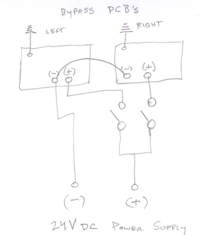
i believe i have something grounded,or hooked up incorrectly in the 24V leg of the circuit. the symptom is that i only get voltage to the relays when both bypass switches are in the on position. if either switch is in the off position i get 0V to both relays. i haven't spent time or thought on this problem yet .i'll take look tomorrow and see if i can figure it out. but any ideas are welcome.
 
didnt get a chance to work on the project today. i dont remember how it is hooked up. i believe i split the 24V of the psu into two legs and wired each in series. i'll check and redo tomorrow. i picked up 1a fuses today for the project. im thinking if you used 500ma at 230. the current will be double at 115V. is that correct? might be the answer to my fuse problem. thanks for all the help
EDIT
this is a diagram of how i first hooked upthe relay boards.i believed they were working fine because i was using only one channel at a time.when i tried both channels at once
i onlygot one channel. i believe i need to lift the ground from one of the boards. i'll do it and get back with results.  sorry if anyone hooked up their unit like this
small.jpg
 
rewired the backwards input pot. seems the input was not the only pot wired backwards. makes sense i guess .did the first one wrong and then did the same with all the rest. rewired all pots but im not out of the woods yet. heater V good. 24V PSU voltage good, relays work as they should. low B+ voltage. here is a diagram of what im getting:

myD-aocvoltages.jpg


the neon bulb in the meter circuit(left side) is not lighting.it was  lighting at one time but went out after i hooked the pots up correctly. i replaced with a new bulb but it is not lighting. the voltage on the left channel at r127 is only 10Vs all other voltages are those  in the yellow on the diagram.

unit (left and right channel)is passing audio (input and output pots working)but not compressing
i  lifted a leg of r128 and r228 isolating the PSU from the rest of the circuit. i am getting around 350Vdc from the supply. shouldnt the regulator be putting out about 250V? or am i getting the corect non loaded V? i'd like to know if i should change the voltage regulatoor rule out the psu as the source of my units symptoms. please  help! ???
thanks chris V
 
Bump. see above. checked for the usual. solder bridges,cold solders,etc all seems ok. switched tubes(that tested good) from left to right channel and left channel put up the same voltages and symptoms
any ideas? please
 
with no load the B+ regulator doesn't work.
what's your (loaded) regulator output voltage?
(just measure the other side of R128).

the neon bulb doesn't need to light (and won't with only 51V).
your left channel for sure has a problem with only 10V.

it is passing audio = good.
not compressing: you need a really hot signal at the input in "stock" mode.
do you have an oscilloscope?
put the probe at the right pin from the stereo link connector.
can you see a signal there?
it might even compress now!
 
Back
Top