You are using an out of date browser. It may not display this or other websites correctly.
You should upgrade or use an alternative browser.
You should upgrade or use an alternative browser.
RCA Ba2A Pre amp qestions & answers
- Thread starter gary o
- Start date


Help Support GroupDIY Audio Forum:
This site may earn a commission from merchant affiliate
links, including eBay, Amazon, and others.
i can not say for sure, it has the thin light brown inter-layer inulation like UTC, but everybody uded that.
I took apart a Western Electric that had a similar core lap job.
the potting compound is usually a giveaway, everybody has their own stink, this stuff is a little different from utc, triad, peerless, langevin.
i will look in the catalog and see if the numbers match anything.
I took apart a Western Electric that had a similar core lap job.
the potting compound is usually a giveaway, everybody has their own stink, this stuff is a little different from utc, triad, peerless, langevin.
i will look in the catalog and see if the numbers match anything.
craptical
Well-known member
How far a throw do you think an A-25 would be?
/Dave
/Dave
craptical said:How far a throw do you think an A-25 would be?
Would work fine.
craptical
Well-known member
emrr said:craptical said:How far a throw do you think an A-25 would be?
Would work fine.
Thanks!
Got some 6C5´s in the mail as well. ;D
/Dave
Hey EMRR are you sure that was not instead of an output transformer you sent me?
It looks a lot like a UTC Commercial Grade - CG - 235 50-200-500 to 80,000 Grids.
The can has the RC-75 or whatever dimensions.
There is an alloy liner in the can, but the lam stacking is more like an output, weird.
It looks a lot like a UTC Commercial Grade - CG - 235 50-200-500 to 80,000 Grids.
The can has the RC-75 or whatever dimensions.
There is an alloy liner in the can, but the lam stacking is more like an output, weird.
It's officially the output. Yes. I have a whole stack of them, and many original preamps using them.
The crimps in the case differ from any UTC I've ever seen. Craft was one manufacturer of transformer potting cases, and many people used their stuff. You see CG type cans and the can generally considered to be Stancor output type in the Craft ads of the late 40's-early 50's.
The crimps in the case differ from any UTC I've ever seen. Craft was one manufacturer of transformer potting cases, and many people used their stuff. You see CG type cans and the can generally considered to be Stancor output type in the Craft ads of the late 40's-early 50's.
Cool, if you are ever under the hood, get the DCR.
I can add it to the chart.
BTW, Wire is #40 for pri and #37 for sec.
I can add it to the chart.
BTW, Wire is #40 for pri and #37 for sec.
I measured 4 of them. Average is 2.6K:120 DCR.
Part # is XT-2747.
A similar RCA output is part #900542-501 (same as XT-2875). I have one of same undetermined manufacture and another made by Hollytran in LA. Both measure 2550:210 DCR. Sec on these is 500.
Note the K-901740-501 (XT-2875-2) is the BA-1A and BA-2A output.
Part # is XT-2747.
A similar RCA output is part #900542-501 (same as XT-2875). I have one of same undetermined manufacture and another made by Hollytran in LA. Both measure 2550:210 DCR. Sec on these is 500.
Note the K-901740-501 (XT-2875-2) is the BA-1A and BA-2A output.
Awesome.
See here:

See here:
abby normal
Well-known member
CJ said:OT, check out the octagon transformer on this BA 1:
CJ you know way more about transformers than me, could that be a UTC "S" series?
Did some experimenting with another members BA-2 clone yesterday. It uses original input iron, and UTC A-25 outputs.
We switched in an RCA output for direct measurement comparison, and the A-25 is microscopically better on the top end, and worse on the bottom end. I'm not sure enough of a difference to hear, in regards to freq. response. The RCA is built on a larger core than the UTC.
The most interesting thing was to see that the original input primary connection, as shown on the schematic (one side grounded), gives a treble peak about 16K. When connected as in the BA-1A, CT grounded or floating, it gives no treble peak. The original BA-2 schematic shows input connection as would be found in this amps normal occupation; turntable output amp, fed by an unbalanced turntable EQ network.
Aha you beat me to it.
But yes, take heed of emrr's observation - very important to proper freq response of the BA-2.
FLOAT (the cold side of the input pri) and ye shall be FLAT again!
Thanks again Doug for pinpointing that problem.
BTW - amp has noticeably different character now - seems richer in the mids, plus no sibilance band dist. Interesting also that A/Bing each channel - hi boost IN/OUT gives no audible difference like it did before. Much better overall this way though. ;D
letterbeacon
Well-known member
*bump*
I'm gearing up to build a BA-2C pre amp, here's the schematic:
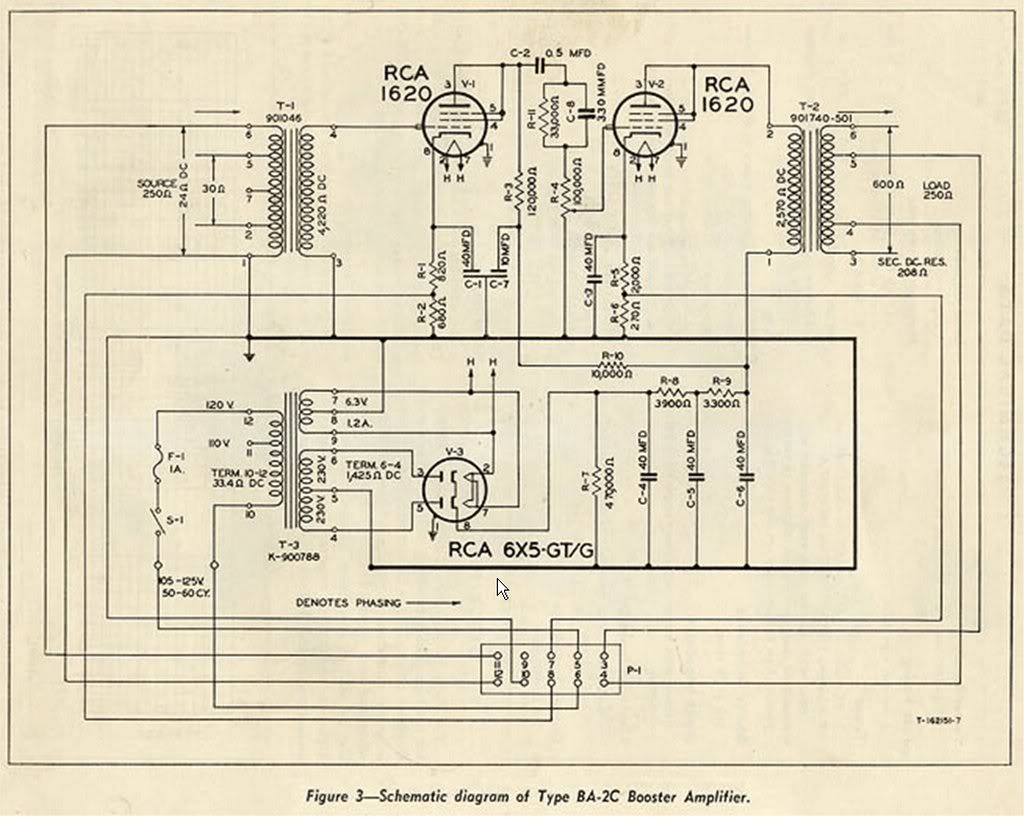
I've drawn out my turret board layout, but I have a couple of questions:
a) I might be able to get hold of a BA-2 output transformer but I don't have an input transformer. I was thinking of going Sowter, what sort of specs should I be looking for?
b) I can't quite make out what the values of R1 and R2 are, does anyone know?
c) Was the original coupling cap between the stages paper-in-oil or film?
d) What voltage rating should C7 be? I know it's a power filter and I know I should be able to work this out with some maths, but I don't know the maths! I know Ohms Law is my friend here, but I don't know what the power or current would be to work out the voltage.
Thanks.
I'm gearing up to build a BA-2C pre amp, here's the schematic:
I've drawn out my turret board layout, but I have a couple of questions:
a) I might be able to get hold of a BA-2 output transformer but I don't have an input transformer. I was thinking of going Sowter, what sort of specs should I be looking for?
b) I can't quite make out what the values of R1 and R2 are, does anyone know?
c) Was the original coupling cap between the stages paper-in-oil or film?
d) What voltage rating should C7 be? I know it's a power filter and I know I should be able to work this out with some maths, but I don't know the maths! I know Ohms Law is my friend here, but I don't know what the power or current would be to work out the voltage.
Thanks.
b) I can't quite make out what the values of R1 and R2 are, does anyone know?
Unless you are wanting to add metering just use a 1.5K (820 + 680)
d) What voltage rating should C7 be? I know it's a power filter and I know I should be able to work this out with some maths, but I don't know the maths! I know Ohms Law is my friend here, but I don't know what the power or current would be to work out the voltage.
You have a 230 volt winding times peak value. 350V is the lowest standard value you want to use. Anything higher is just fine. Same goes for all the coupling caps.
a) I might be able to get hold of a BA-2 output transformer but I don't have an input transformer. I was thinking of going Sowter, what sort of specs should I be looking for?
Anyone of their dedicated mic to grid transformers should work. The REDD 47 model or the generic mic to grid (4935). They will not have the same ratio as the original but this is only a small difference. I would email Sowter and ask about recommended resistive loading on the secondary - ask what the expected input impedance would be if left unterminated into an open grid as the original is.
letterbeacon
Well-known member
Great, thanks guys!
Attached is my turret board layout for the amp (excuse the dodgy drawing). I'm going to be using screened wire for the grid connections to the 1620s. Is it ok to solder the screen to the ground on the input XLR or should I try and get a connection to one of the two star grounds?
Attached is my turret board layout for the amp (excuse the dodgy drawing). I'm going to be using screened wire for the grid connections to the 1620s. Is it ok to solder the screen to the ground on the input XLR or should I try and get a connection to one of the two star grounds?
Attachments

letterbeacon
Well-known member
This might be a stupid question, but could I add a DI by connecting a jack to the grid of the 1620 with a couple of resistors like this:
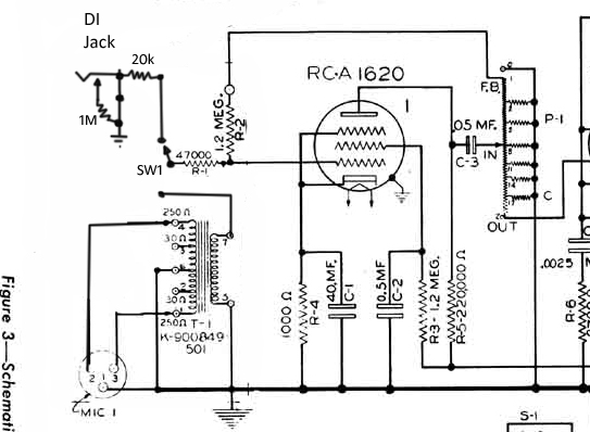
Is this really for an OP-6? Or for your BA-2 clone?
If for your BA-2 you can do a standard type DI with a 1M resistor from grid to ground - omit the series resistor. Should work just fine.
Theory wise doing that for an OP-6 probably won't be as straightforward as a BA-2. Someone else will have to answer.
I probably won't be the only person to advise against hacking a real OP-6 for a DI - even if it works without issue. I would say use a DI box for instrument use.
Similar threads
- Replies
- 2
- Views
- 263
- Replies
- 30
- Views
- 2K