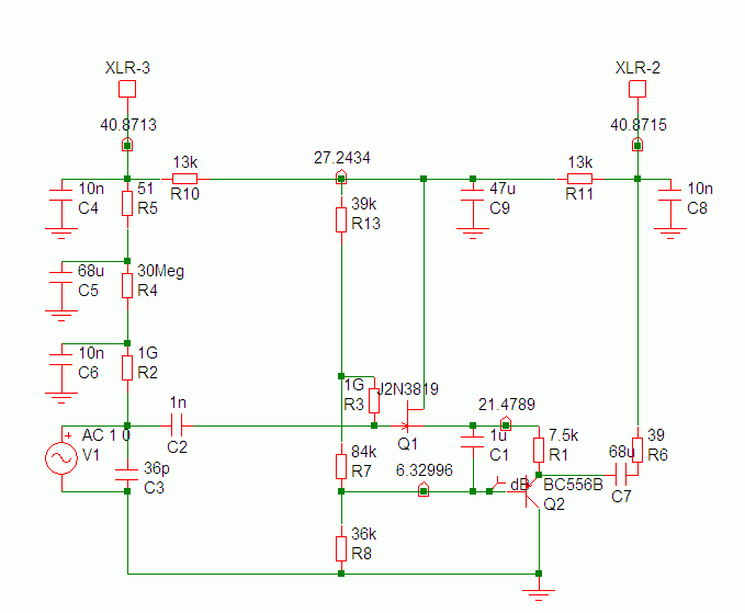
[Slightly different #2] Oktava MC/MK-012 circuit elegance ?

GroupDIY Audio Forum

Help Support GroupDIY Audio Forum:

This site may earn a commission from merchant affiliate links, including eBay, Amazon, and others.

clintrubber

Well-known member
Joined
Jun 3, 2004
Messages
5,984
Location
The Netherlands
My eye fell onto the PNP in this circuit:

http://www.sdiy.org/oid/mics/Oktava-MC-012.gif

The 1 uF cap makes it a push-pull.

The 7k5 seems to function as a source (/emitter) resistor for both devices at the same time.

More 'double functions': the capsule polarisation voltage is derived from pin#3 and at the same time 'a fake output' (impedance matched to 'the active output') is realized: the 51 & 30M resistors and the 68uF that both joins in mimicing the output impedance as well as smoothes the polaristion voltage (followed in this by the 10nF & 30M).

Bye,

Peter
 
Yes, very elegant. The 1uF in fet source should also bootstrap the input a very very very little?
 
I believe we looked at this circuit here in the past. It is kind of like a white follower but with a fet and a PNP.
 
[quote author="tv"]Yes, very elegant. The 1uF in fet source should also bootstrap the input a very very very little?[/quote]
Nice one... :thumb:
Yep, in principle it does, but like you said, because of the numbers it won't be very much.
 
[quote author="Gus"]I believe we looked at this circuit here in the past. It is kind of like a white follower but with a fet and a PNP.[/quote]
Hadn't seen the thread & hadn't realized that yet, but indeed...

Here's a more straight-on translation of White (tube-to-Si, sorry for size),

ef3.gif


let me think a bit more why they didn't do it like that but went for the PNP.

Regards,

Peter
 
Using the PNP removes the need for the top collector resistor needed to generate a signal used in the 2 NPN circuit you posted

The 2 npn has a constant current part that is modulated via the inverted signal off the top NPN collector. Signal generated from R3

The 012 having a PNP at the "bottom" can use the noninverted signal from the source from the SF FET Signal generated from the 7.5K

The oktava 012 is a nice simple circuit that does not sound bad for a transformerless microphone. I have built a variation of it for a LD microphone.
 
[quote author="Gus"]Using the PNP removes the need for the top collector resistor needed to generate a signal used in the 2 NPN circuit you posted

The 2 npn has a constant current part that is modulated via the inverted signal off the top NPN collector. Signal generated from R3

The 012 having a PNP at the "bottom" can use the noninverted signal from the source from the SF FET Signal generated from the 7.5K[/quote]
Hi Gus,

All true observations for sure, that's how it works, but one could still wonder why they went for this instead of 'same stuff active devices' ?

The reason might perhaps simply be the cost: I figure a realisation in the 2 NPN 'D.Self-style' but now with two FETs would have increased the cost of BOM: a FET i.s.o. the BJT (and the additional resistor and perhaps some more).

Regards,

Peter
 
[quote author="bcarso"]What was the original FET?[/quote]

Some Russian type. Actually various Russian types; there's always some variation & fluctuation in Oktava mic circuits. Brands change, transistor types change, and resistor values change, too, often as a result of transistor type changes. A happy mess :grin: I quite like their circuits. The actual realizations are sometimes debatable, but the designs are quite nice & competent, I think.
 
[quote author="bcarso"]Russian FETs? Hmmmm....

Do you have any idea what, roughly, the parameters were? I guess I tend to question the substitution of SK170s into circuits not designed for them.[/quote]

I don't know anything about the parameters. All I can say is that they are adjusted for roughly 10V between S and D, at least in other Oktava circuits. I'm not sure I ever measured the bias points in this particular circuit. I have some MK-219s and MK-319s that I recently measured, and the source was always around 1,5V and the Drain about 11V. Various slightly different FET models were used (the same types as in the 012 circuit, I think) and it looks like they chose the drain resistor according to the FET type and hand selected the source resistors (there are two) for each individual mic.

Since the resistors are factory selected, I never bothered to replace the FET. They're pretty low noise anyway. If I were to replace them I'd probably opt for the 2n3819 which might be a closer fit than the 2SK170. The MK-219/319 is kinda similar to the Neumann KM84 circuit, in which a 2n3819 was used for a while.
 
Found a note I made about the 012.

One fet was marked ABM7

I have seen metal and plastic case fets in 012s.

A 219 I have has a plastic TO92 case fet marked B6L0 with a white dot on top., I think it is 6 it kind of looks like a 6 and 5 together
 
The original FET in the 012 circuits I've seen was marked "ABM7", whatever that is. The drain measured 26V and the source measured 20V.

The FET in my 319 is either marked "BGN1" or "B6N1" (can't tell if it's a "G" or a "6").
 
[quote author="Flatpicker"]The original FET in the 012 circuits I've seen was marked "ABM7", whatever that is. The drain measured 26V and the source measured 20V.

The FET in my 319 is either marked "BGN1" or "B6N1" (can't tell if it's a "G" or a "6").[/quote]

Assuming it is Cryllic it is a 6. The russian g is Г ... B is V, H is N and so on...

I'm fairly sure you know that....

The last 2 MK319 that I modded both had 7bn2 (7БН2) Fets.

Regards, Ethan
 
> The 1 uF cap makes it a push-pull.

No. It's not push-pull, not remotely a WCF.

The current in the 7K5 is constant. No AC current, therefore no "pull".

It is a JFET source follower driving a PNP emitter follower. The PNP's emitter impedance is near 20 ohms, so 7500/7520= 99.7% of the voltage at JFET source is bootstrapped off. The JFET thinks the 7K5 is over a Meg. The JFET does drive the base resistors, about 28K, but this JFET can do that at near unity gain, ~~0.993.

The added clever bit is they both use the same supply current. Makes sense when we have huge voltage but small current. Neither stage needs much more than 10V, but would benefit form a mA or more.

Analysis is tricky. Assume base and gate drops are zero. Then voltage on the 7K5 and 84K are equal, currents are in a 84/7.5 ratio. The 84K is in a resistor string, so the JFET-7K5-PNP will also act much like a resistor string with 7.5/84 the total resistance. The total is near 13K. This is in series with the 13K up above and the 3K4-6K8 Phantom resistor. It all draws about 1.6mA. Capsule bias about 21V.

Peak output to 200 ohms just 0.3V, but 200R loads are rare. 3V into our usual 2K load. Maybe 4V into infinite load.

Output impedance about 60 ohms.
 
The Gefell is not push-pull either. Triple Darlington, complicated by a JFET and capacitor coupling. V1 is surely for HPF as you say.

It also stacks the capsule bias oscillator with all three signal transistors.

This designer must be a wizz with mazes and jigsaw puzzles.

This one at least sucks both XLR pins correctly. Unbalanced drive is one thing, taking ALL your supply current from one pin as the Octava does is another thing. Picture a transformer input with 48V through 3K4 to a center-tap. - EDIT- WRONG!
 
[quote author="PRR"]

It is a JFET source follower driving a PNP emitter follower. [/quote]

I'm relieved, cause that's what I always thought it was until this thread came up. :grin:

[quote author="PRR"]Unbalanced drive is one thing, taking ALL your supply current from one pin as the Octava does is another thing. Picture a transformer input with 48V through 3K4 to a center-tap.[/quote]

Are you sure? When I entered the circuit into a simulator a while ago, the voltage drop on both XLR-Pins was equal. :?

mc012sim.gif
 
Back
Top