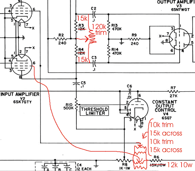
6sk7 balance pot to Federal Limiter

GroupDIY Audio Forum

Help Support GroupDIY Audio Forum:

This site may earn a commission from merchant affiliate links, including eBay, Amazon, and others.

cannikin

Well-known member
Joined
Feb 8, 2005
Messages
1,009
Location
Seattle Washington
Hey guys,

I really want to implement the 6sk7 balancing pot in the Federal I think it will help with some lingering issues on my federals.  I have a bunch of 6sk7's but they are not matched and all sound extremely different, I don't want "pay" for matched pairs or something.  the schematics are similar in some ways but I want to make sure its possible and get some peoples thoughts.  Input greatly appreciated.

Federal Schematic: http://www.waltzingbear.com/Schematics/Misc/AM-864.htm
 
very cool thanks!

Oh I sent you a PM about the OD3 voltage 149.6Vdc

I think your really gonna like the 1954 design, it is really blowing me away right now.
 
It may seem dumb, but there's nothing better than having a dozen tubes to pick your pair from. You should be able to get a match from the pile you have, if they are all new tubes. Even if all good used examples. There's something wrong if they all sound different, aside from hairsplitting detail. Screw paying for matching, which you won't find available anyway, do it yourself in the unit in question. That's the only place any test result will have meaning; in circuit, in THE circuit. That's why Gates SA-39's and RCA BA-6's have tube cathode current metering built in.

Oh yes, the cathode balance pot is a thing to try. Or a 25K linear (properly rated) in place of R3/R4 if you find a cathode pot causes other problems.

Did you get your hum issues sorted out, or is that what we're talking about here?
 
Yes humty dumbty hum - makes the federal useless (federals being humty and me dumbty :grin: ). the reason I ask is with the 1954 limiter build; that balancing pot set at the right position totally kills any low level/minor hum I might have. So I was thinking to implement the same thing on the federal.... hum pot/dc heater on the 6sk7's/6sk7 balancing pot. I know its over-kill but the combination gives me different methods and options to deal with any hum issues.
 
yeah, added tweak options can make or break a session when a tube acts up. I found that SA-39's without the first stage DC filament implementation liked to go from usable to unusable from one day to the next, and no amount of tube swapping/matching would cure it. I still think that Federal filament implementation is totally screwy if you expect to pass 60/120 Hz without audible hum. I'd wire in a more standard manner or go DC.
 
Both cathode and screen grid pots balance in 2 different points: min and max gain. If tubes are well matched they can't be identical absolutely, also transformers are not ideal, so balancing will be needed anyway.
 
here´s a plan... don´t mess with the cathode:

balance_mod2.gif


sorry for the mess, but it should be readable.
 
Ok, if you downloaded the pics I´ve posted earlier, delete it, because there were errors I´ve spot after posting. That one above should work now.

if you can´t find a 120k trimmer (should be hard???) you could try 22k plate resistors for R3 and R4 (instead of the 15k on pic) and a 50k trimmer (in place of 120k on pic), for a very close value to the originals, but 50k trimmer should be a little higher power.
 
I don´t know if it will help at all with your hum though.. How bad it is? This mod is more for killing compressing THUMPS, you know...

For hum killing, simply messing with the power transformer position might help. Oh, yeah, and grounding...
 
Since anecdotal evidence seems to point toward the later version of the schematic that has 47K resistors in R3 & R4 being more stable, could the same thing be achieved with two 75 ohm resistors and a 250k pot?

Pros? Cons?
 
hm... was not the 47K the earlier Version?
See Manual page 6 (pdf page 8) 30.4
And did you realy mean 75 Ohm? Seems low for everywere I can think of.
 
And did you realy mean 75 Ohm? Seems low for everywere I can think of.

I meant 75K.  Sorry for the confusion.  

The idea being that the resistors plus the parallel pot equals somewhere around the value of the original circuit.

was not the 47K the earlier Version?
See Manual page 6 (pdf page  30.4

Looks like you are right.  I stand corrected.  But since we are looking at this, why would they have changed this value?
 
PRR explaned nicely in this tread:
http://www.groupdiy.com/index.php?topic=10097.0


................................
"> I think a regulated power supply would be a good idea.

For a simple sidechain and broadcast-standard limiting level, you need to regulate, only the vari-gain stage (and only the G2 of pentodes). The output level rises until the gain is reduced enough. The amount of grid voltage needed for any given gain reduction is a function of plate/G2 voltage. 12AU7 working at 100V on the plates will give a lot of gain reduction at -7V on the grids; if run at 300V on the plates it needs -15 or -20V on the grids for similar gain reduction. Or simply: 1dB output level accuracy needs 10% supply
regulation. In systems that assume fairly steady wall-power, or that don't need consistent limiting level, unregulated supplies worked fine. +/-20% line variation is +/-2dB output limiting level variation: if you just don't want speech to splatt, that's plenty good. If the wall wandered more than 20%, the tube heaters would be unhappy. If the limiter feeds a loudspeaker amp on the same wall power, the
limiter "should" track wall-power wanderings, because the power-amp max output will be shifting too. Finally if you set the limiter
by-ear every time you use it, exact limiting level consistency is pointless unless you also have large wall-power variations during a take or mix. (And if you do, that may be more a problem for other gear than for the limiter.)

If you try to run the vari-gain stage on a low voltage dropped from a high voltage through a resistor, you get a different type of limiter. As vari-gain stage gain drops, stage current drops, voltage drop in the resistor is decreased, supply voltage to the stage rises. This works against you, but is not necessarily bad. Many-many tube limiters work with high-value plate resistors and the plates soar from 60V at idle to 200V at -6dB GR to 230V in deep GR. This softens the knee but can be somewhat compensated by increased gain to the
rectifier and increased rectifier threshold voltage."
..........................

So you probably get a softer knee with the 45K´s wich was not what you want in a Broadcast Limiter.
If you decide to experiment with that please keep us informed about your resultes.  
 
I knew the answer was here somewhere, and I should have known it would have come from PRR. Thanks for pulling that quote for me.

I will experiment and will most certainly report back.
 

Latest posts

Back
Top