Double ground planes

GroupDIY Audio Forum

Help Support GroupDIY Audio Forum:

This site may earn a commission from merchant affiliate links, including eBay, Amazon, and others.

Freq Band

Well-known member
GDIY Supporter
Joined
Jan 5, 2006
Messages
608
Location
Electra City
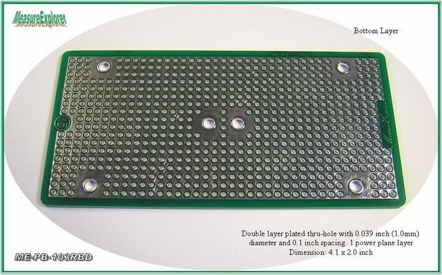
I have some prototype boards that have 2 separate ground-planes - top and bottom.

Would it be wise to use one plane for "power ground", and the other for "signal ground".....and which side should be "power ground", component-side, or solder-side ?

Or, should I use the planes in a different arrangement ?? (for line-level circuits)

thanks,

=FB=
 
I always use separate planes If I have the luxury of doing so.
I make the plane closest to the components (top) signal ground
and the bottom power supply ground. I connect them together at one
point only at the power input common.
 
nah, low speed signals don't need separate grounds, just proper layouts to keep the current sinks near the ground termination.
 
for signals more than 1Ghz?

Anything lower than that is typically considered low speed in the RF signal world.

Power ground can be for both SMPS and linear devices.. That's the equivalent to having digital and analog on the same grounding arm from the star termination, and can generally cause issues.

Analog/digital grounds are generally separated because the switching of the digital circuits causes swells of current through the ground planes. These currents can couple through the analog parts into the signal path, especially through opamps and linear supplies (which are really just power opamps..).

That being said, high speed signal reception is generally very sensitive to noise simply due to it's high speed nature. Noise is essentially a high speed signal. Now if you have signal traces routed between power and ground planes and both planes have switching currents running through them, then that hash can and will capacitively couple into your highspeed traces. At this point you have just ruined any gains you could have received from separating planes.

It's much more important to decouple properly and match impedances in order to minimize noise ingress than to worry about planes most of the time. If the circuit allows noise to get in, then there is no grounding setup that will help you, even if you separate planes.

If those are "professional" proto boards from a manufacturer, then they likely had their intern/1st year engineer lay them out. Even if a seasoned veteran layed them out, they could have fallen victim to one of the many caveats of a PCB designer, or they simply concluded that the secondary plane didn't make any difference to the circuit and left it there to save routing money.

I'm not saying that you shouldn't try, you could find something that could help the rest of us!
 
Thanks for your explanations.
These have 1mm holes @ 0.1 inch spacing.

38ce_10.jpg


...very handy for point-to-point wiring, ground planes on none, one or two sides.
http://stores.ebay.com/MeasureExplorer

I also have a different brand that has most of the plane epoxy coated, which makes it much easier for soldering, and not allowing accidental "bridging" of the pads to the plane.


=FB=
 
[quote author="Freq Band"]I also have a different brand that has most of the plane epoxy coated, which makes it much easier for soldering, and not allowing accidental "bridging" of the pads to the plane.
=FB=[/quote]

The Twin Industries stuff with two planes I found difficult to use because of the ease of shorting things. The coating is a good idea.
 
Well, I've had plenty of times where power ground and signal reference ground planes were quite helpful in reducing noise, especially in mixed signal and power level environments.

Many times a plane can be avoided for the reference, but sometimes it's just as easy because a power plane needs to be balanced out in the layer count...
 
From what I've read (or attempted to..) about the delicacies of where to put a ground plane, and where not to put a plane.....reminds me of the novice trying to understand and build an antenna.
Most of the time you get so-so results.
Once in a while you hit it perfectly.
And sometimes you really f-ck it up.

=FB=
 
[quote author="Larrchild"]Which ground should the metal standoffs which hold the board be connected to?[/quote]

I would be inclined to connect chassis to power ground but YMMV. It could depend on what's inside the box and what touches the chassis.

JR
 
[quote author="Freq Band"]From what I've read (or attempted to..) about the delicacies of where to put a ground plane, and where not to put a plane.....reminds me of the novice trying to understand and build an antenna.
Most of the time you get so-so results.
Once in a while you hit it perfectly.
And sometimes you really f-ck it up.

=FB=[/quote]

In very sensitive designs there can be some experimentation involved. If a design doesn't work you usually know why, after you see it not work. The hard part is seeing it before you do it wrong.

Large ground planes are a shield, antenna, and low impedance conductor. The difference between a shield and antenna is pretty much the impedance to ground.


JR
 
JohnRoberts:
Large ground planes are a shield, antenna, and low impedance conductor. The difference between a shield and antenna is pretty much the impedance to ground.
Indeed.
A ground bus connected to chassis at one end is better for audio, but forms an antenna at some vhf/uhf freq. They are at cross-purposes at times, RF and audio.
 
Back
Top