>
it's a guitar pickup. ... With a volume pot.
5K+5H, loaded in ~~200pFd and 250K(?) pot, the pot wiper loaded with ~~300pFd of guitar cord, gridleak, grid capacitance.
I did the curves long ago, and if the guitar pot is 250K and anywhere in the middle, it's basically 60K resistive and the cord-capacitance does not influence the pickup winding resonance. So any amp-jack over 270K and under 150pFd is all the same. If you work the pot full-up, you might like 750K-1Meg and <150pFd.
Without the pot, there is a sub-octave resonance peak in the 3KHz-6KHz range, sensitive to cable length. The amp input resistance affects the height of the peak, but high resistance gives a very narrow peak, like 3 notes (actually harmonics).
A very low resistance will suck-off highs due to coil inductance. There is ample empirical evidence that 130K is "high enough" for most guitar tone. Look at the Fender 2-jack input affair which became common when humbuckers appeared and were overloading inputs. The lo-gain jack gives two 68K in series to ground with grid tapped at the halfway point.
Keep your resistance well above 100K, it's all the same. For non-active guitars, capacitance is all about the guitar cord. Don't wet-dream "high impedance" and then use a 30-foot cord. Even a 3-foot cord is 90pFd, and fairly awkward unless you sit with your amp at your right hip.
Jack's site has an overview.
Douglas Brown's paper at U Urbana has carefully measured values. Note however that cable capacitance is not included (yet generally essential); real stage use does not yield 9KHz and 850K.
And you do NOT want 9KHz response. The overtones of a string (or pipe) are not on the harmonic series. You "need" a low-pass to knock-down inharmonicity. The speaker does some, but high partials in the amplifier will intermodulate into the passband, with really unharmonic result. The pickup top-resonance is as important as the diameter of a flute or clarinet, or the thickness of a reed, factors which blow-musicans wrestle with.
More at
Daten & Resonanzfrequenzen von Pickups, also
BuildYourGuitar.com
------------
>
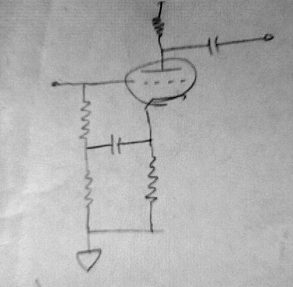
a single toob may be used as a cascode. The problem solved.
Analysis suggests that input C of the tube is not limiting. However guitar input stages tend to run near overload even with 250V supplies; a cascode suggests ~~500V supply between stacked triodes and increased gain. Also I am believing that the curvature of 12AX7 is part of "the sound"; a cascode has a different curvature. And in a real-world, every dollar and ounce in a guitar-amp hurts your income and your shoulder. Solving a non-problem is not the best use of a spare section.