[ACMP investiupgradifications] All things PREAMP

GroupDIY Audio Forum

Help Support GroupDIY Audio Forum:

This site may earn a commission from merchant affiliate links, including eBay, Amazon, and others.
Here's a kick in the crotch

http://www.groupdiy.com/index.php?topic=31105.0

apparently these got guys got it together  and  / or
benefited from the chance grp beta buy

I Don't imagine we'll get anything from the chinese now
in terms of replacement parts [ well maybe on the next
order but we'll always be an order behind on getting the right things ]
 
Bo from Golden Age already had his prototypes when I ordered my gb 81´s, wanted the eq...
He offerd me one of those to buy back then but as I just had ordered...

Matti
 
As audioforge points out , it appears to be the same design
so why they'd give us ones without the off postion ???
going backwards , unless these were sitting around ,

not surprizing for the chinese to copy things and resell
them [ sometimes making improvments along the way
or as someone else buys it ]

curious question would be who started this design ,
Bo's seems to take into account some of the problems
of the acm ones
 
audioforge said:
btw there no way to avoid the short between 6/7 position in mic mode( when the b284 ampcard add the extra gain stage) so flip to line before switching or build a new 3 deck 22 pos.attenuator.....
audioforge
I just saw that part of your post.. oops. that's why I asked my stupid question after.
Is there a source for that switch? I bought some similar ones on ebay for my PM660 but never saw a 3 deck one. Ideally China would send those for FREE, but I won't hold my breath... so if anyone knows where to buy this (for cheap) I'm looking for two.
 
Hey Maxwall, maybe a new problem/solution for '81 owners?  Check out dgatwood's posts on page 284 and 285. He seems to think he doesn't have the transistor problem but that the noise it is mostly induced. And then some board connector problems too, it seems. Hopefully he'll find some new, helpful, info. Good luck all.

http://homerecording.com/bbs/showthread.php?t=180964&page=285
 
Added observation as copied from Black Market:

druedger said:
rodabod said:
If anyone has received preamps here, or has read about the hum problems, if you have time, then could you contribute any thoughts you have on fixes?

I just put my unit through its paces last night, and the um is bad.  I'm sure others have seen posts elsewhere about this, but the main issues are that with the EQ engaged there is a nasty ground loop buzz when the notch filter selection is set to 360 Hz.  It seems to be across each frequency selection for that switch.  I also noticed that even the hi pass filter has hum problems as well.  As you continue to move the switch towards 300, the hum gets progressively louder.  The worst problem appears to be a nasty pop that occurs when increasing the gain on the gain switch.  Somewhere around 8 o clock on the dial it pops hard.  It's so loud that it hurt my ears with headphones on.  If it had gone to my monitors, there's a good chance it could have damaged the speakers.  It's that bad.  So keep that in mind when you get your units.

Does anyone have a schematic for this?  When I got the unit I pulled the cover and noticed that there is no star grounding scheme for all the card connections internally.  I'm thinking of redoing the internal grounding, but I'd love to see a schematic so I can do it properly.  I'm sure I can suss it out just by tracing wires and such, but a schematic would make it much easier and would save some time.

Chance, is there any way you can make schematics available for these units?  I hear the ACMP-81 and ACMP-84 units have the same hum problem.

BTW, question for schematic already answered.
 
I'd hesitate to use the term "ground-loop buzz" until it's confirmed that the hum is caused by a ground-loop. That said, it's certainly potentially a problem.
 
Two notes from my side.

1.  Hum/Buzz

After replacing the transistors in one of my 81's with the BC's I still had hum/buzz... Rotating the transformer changed the quality of the buzz but did not eliminate the fault.

I made up a 10 conductor test extension cable to remote the power xformer and that has solved all of the buzz issues. Nice and quiet with EQ engaged.

I tested the remote xformer with an 81 that has the original trannies and still have some oscillation.

My conclusion is that for the best and most reliable results the power transformer needs to be outboard and the transistors need to be swapped.

I'm going to look into putting together a small project box, some 10-conductor-16awg cable, and dedicated 10-pin connectors to connect up the power transformer for each of my units... As well as replacing all of the eq board driver transistors with the recommended BC's..


2. The OFF-POSITION POP / Second stage shorting issue...

Just wondering if anyone thinks that removing the highest gain setting from the switch/unit, inserting an OFF position at the point where the second stage kicks in, and respectively moving up the resistor network one position would eliminate the "pop"... I personally don't mind losing the highest gain setting to accomplish this. That would be some fairly easy res-older and jumper work if it would resolve/remove the pop sound.

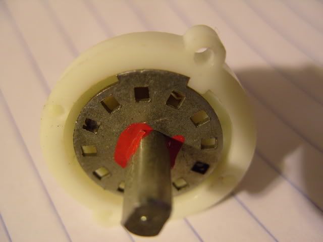
I'm also wondering whether the switch is actually a 12 position switch with a mechanical stop at the 11th position and it might be possible to rebuild it with an off position and all of the original sensitivity positions. The sensitivity switch does look the same as four others which are six position 3 deck switches.... I'm guessing that those might have a stop at the 6th position. Any thoughts about that?

Cheers,
jonathan
 
good news... not an ideal solution for '81 owners but.... it's a step in the right direction. Thanks for doing the tests. Let us know if this solves the second units noise problem.

sorry, no help on the switch thing... I was planning on getting a whole new switch like the Golden Age pre... is there a source for that that anyone knows? Or anything similar (cheap chinese switch, not Elma, etc)
 
The Rotary switches on the 81's (prolly the 73 and 84 too) are modular multi-deck 12 position switches (14 pads for each deck)..

All of the rotary selectors on the 81's use the same switch with stops and the number of decks configured appropriately...

On the preamp board it looks like 13 of the 14 pads are used The 12th position/14th pad is unused.

On another note, these switches may be relatively inexpensive for use in other projects.

Cheers,
jonathan
 
0dbfs said:
The Rotary switches on the 81's (prolly the 73 and 84 too) are modular multi-deck 12 position switches (14 pads for each deck)..

All of the rotary selectors on the 81's use the same switch with stops and the number of decks configured appropriately...

On the preamp board it looks like 13 of the 14 pads are used The 12th position/14th pad is unused.

On another note, these switches may be relatively inexpensive for use in other projects.

Cheers,
jonathan
I just took the gain switch from my 81 apart. The stops are not adjustable. It'll require a Dremmel and you'll need to make sure you don't remove too much.

I was hoping to gain the extra position, then just move over the 2nd gain stage resistors by one position and point to point wire the highest gain resistor.
I think the "off" position will need a resistor to B-, or ground. I'm not sure how the original 73 was wired.

Probably just easiest to sacrifice either the highest 1st gain stage position, or the lowest 2nd gain position for the off position.

S1052286.jpg
 
From Homerecording forums:

DGatwood said:
Further analysis on the hum:

I'm definitely seeing some oscillation in the preamp circuit. Replacing the transistors probably will fix the problem, but I'm not entirely convinced that this amplifier circuit oscillation is inherent with the parts chosen. I'm seeing too many obvious problems with the board layout to jump to that conclusion—places where they could easily have dropped in an additional star grounding via a case screw but didn't bother to do so, for example.

I'm also seeing ground traces that are no bigger than the V+ and signal traces. They really should be. On a board like this, I would have expected every board to have a ground plane. That means a double-sided board in which one entire side is a giant ground trace, with every screw passing through a plated through hole connected to that plane. Sure, that ground plane might have the occasional V+ trace running up through it, with gaps around components where the leads go through—maybe the occasional extra trace where jumper might be used with a one-sided board—but otherwise, pretty much a solid copper ground plane on the entire face of the board.

When I looked at this board and didn't see any traces wider than about an eighth of an inch, I quickly became concerned. On further analysis, the entire 24V ground bus for the circuit is only grounded on one end, and that's the end closest to the humming toroidal monstrosity. Having more than a foot of ground between one end of the circuit with a trace width of 1/8" means you're probably between 0.05 and .1 ohms of resistance, depending on how thick the traces are. (No, I'm not going to measure them.) When you're dealing with circuits in the presence of that much EM, even that tiny little bit of resistance counts. A lot.

Needless to say, this is a big reason that the circuits are oscillating. When circuits like this oscillate, what's happening is that some of the output (which contains 60 Hz hum) is bleeding into the voltage lines for whatever reason. The result is that the signal below some frequency is getting boosted massively---equivalent to the maximum gain for the transistor (as opposed to a controlled feedback loop with a resistor in it). Now all the boards have capacitors on the voltage lines to cut down on this, but they need an excellent ground for this to work.

So as a ten second test to see if the grounds suck, I tried hooking up a .47 uF capacitor temporarily across the +24 and 24V ground connections on the right end of the rightmost jumper board. It didn't do anything. Then I tried the same thing, only using a wire wrapped around a case screw for the minus side and the hum dropped in half. So basically whoever did the board layout on this thing screwed up. There simply should not be that big a difference in ground potential between two electrically adjacent boards.

Grounding the foot-long ground bus between the upper and treble boards made the biggest difference. By itself, this cut the hum fairly dramatically. Soldering a capacitor at the right end of the right jumper board between the +24V and the 24V ground and a grounding wire between the 24V ground and a case screw knocked it down further. At this point, with proper cable placement, I'm at probably about a tenth the hum. It's still humming, but the level is close to that of the 73s. Getting closer.
 
Thanks for posting.

In all respect, in general & imho DGatwood is overemphasising the importance of BIG groundtraces.

As long as it's not in common then a bit of additional resistance wouldn't hurt.

In general and if possible, w.r.t. crosstalk etc it's better & more effective to approach grounding by wisdom (separate branches & star-star-star, might be relatively small) than by brute force (big wires, ground planes).

When you can't separate, yes, then go for The Big Wire.

Regards,

  Peter 

 
Peter, I've replied over there. Basically suggesting lifting the board grounds and replacing with a star ground.

Also, pointed out that oscillation often manifests itself as hum in the audible range (when it's not motorboating or whooshing). Sounds like the transistors should still be swapped too though.
 
Nice work everyone.

So far I'm thinking that the transistor swap, sorting the grounding and moving the PSU trafo out of the box is the best plan for silence and not too intensive as a mod.

The gain switch is a bit of a bitch though. Maybe that board can be redone with a new switch.

-T
 
Tom, there were some tests made to see how much the PSU was actually responsible, and it's not really clear yet from what I can tell. It's certainly hard to say when the units are oscillating since it leads to so much hum itself (which can easily be triggered or retarded by moving cables and the transformer itself).

I really want to get hold of one of these so I can put some time into figuring out what's what. For instance, if someone could swap the transistors and run off a bench PSU, then we'd have a better clue as to what's going on.
 
Absolutely mate, just going on 0dbfs post above, sounds like moving the toroid solved some issues. I've not had time to really follow the threads so am not 100% on the real faults etc.

The minute I get one I'll try it on a bench PSU.

-T
 
Hey Roddy, thanks for consistently reporting on this. I too am looking forward to you getting your hands on one, as well as the rest of the hard core guys here, since I trust you guys will get to the bottom of this.

I am wondering though, maybe these toroids are bad? I remember reading in the EZ1290 thread about 3nity fixing Bluzzi's pres. They had hum which was caused by a bad toroid. Maybe these cheap China toroids are emitting more crap than a decent toroid would/should and maybe swapping it with another would help (instead of taking the PSU out of the box)?  In final costs it would maybe work out about the same, if you add up the separate enclosure, multi-pin connectors, cable, etc... and would be more elegant since it would be in the same box. Wishful thinking?
 
I agree, it might be worth trying a different transformer. We'll just need to see what comes from testing these boxes when we gte them.

A lot of the broadcast audio kit at work uses toroidal transformers in mumetal cans. It might be an option to use a smaller model in a can in this case.
 
1.
I've got 4 81's and have swapped the transistors in all four of them (ie; removed original TO-92's and replaced with recommended TO-30's).

2.
I tested the location of the toroid using three tests:
A-> Inside the box.
B-> Hanging out the back of the box.
C-> About 2 ft from the box with a 10 conductor jumper.

As expected, A was the worst, B was in the middle somewhere and C is the best.


DGatwood said:
Further analysis on the hum:
Grounding the foot-long ground bus between the upper and treble boards made the biggest difference. By itself, this cut the hum fairly dramatically. Soldering a capacitor at the right end of the right jumper board between the +24V and the 24V ground and a grounding wire between the 24V ground and a case screw knocked it down further. At this point, with proper cable placement, I'm at probably about a tenth the hum. It's still humming, but the level is close to that of the 73s. Getting closer.

3.
Just now I jumpered the 24Vdi connection on the rightmost jumper-board to chassis/mains gnd and bypassed +24V and 24Vdi (also at the rightmost jumper-board) with a .47u cap while the toroid was still in the box (original position toroid with upgraded transistors):
There is a very slight change in the hum for the better but not much. :(
I'm interested in keeping an eye on and testing other upgrades to the grounding to find the best combination of all.

4.
The writing on the toroid appears to label it as a:
PRI:
0-115
0-115

SEC:
16-0-16
0-26
0-26
0-45

That's what it measures unloaded as well (at least on the 115 mains setting).

Cheers,
jonathan
 
Back
Top