Balancing Tore Seem F2000

GroupDIY Audio Forum

Help Support GroupDIY Audio Forum:

This site may earn a commission from merchant affiliate links, including eBay, Amazon, and others.

Jolle

Member
Joined
Apr 14, 2008
Messages
18
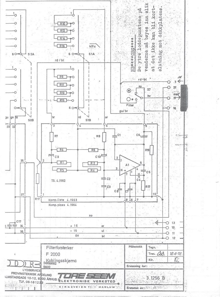
Hi, I am racking a pair of 1970's Tore Seem F2000A EQs, and was planning on using this circuit (originally Calrec I beleive) for balancng in/outs using 5532 opamps.

The unbalanced TS F2000A impedance specs are:
input imp 2k min
output imp 0 ohms series with 100uF, load 600 ohms min

My questions are:
--Do I need to alter component values to match the TS specs, or is it OK as it is?
--What value is recommended for R3 - should it be a trimmer, and if so how big?
--Will an OEP A262-A6E (1+1-1+1 600ohm in parallel) do as the output tranny instead of LL1517? They're kinda pricy...
-- Do different supply voltages make any sonic differences in regards to the 5532AP (TI)? The +/- 15V required by the filters are within its operating range, but then again this is specified as anything between 3 and 20V. I.e., does it sound better at a given supply voltage?

Thanks in advance for any input on this build.
 
..Or just a simple specific: What substitutes a LL1517 the best as a line output transformer, the OEP A262 A6E or teh A2E? The ratio from the A6E matches the 1517, but when looking around in here it seems the A2E is much more frequently used in this position. If anybody has any experience with the above balancing/debalancing circuit from Calrec, I would be very grateful for any ideas as I am about to etch the PCB:)
 
Simple balanced output made of two inverting op-amp stages will do the job. Or you can use one of those balanced drivers like SSM 2142. Transformer is probably not necessary in your application. Do you have a schematic for your EQ?
 
Yes I have the schematic in hardcopy, I will upload them when I get around to scanning them. They come from a broadcast console used by Danish National radio, and are identical to the unit discussed here.

I know I can balance the units in other ways, just wanted to do it close to the way it was probably originally done. I am just in doubt if there will be any gain/impedance issues using the calrec circuits on the tore seem - and which OEP transformer will do the best job. [/url]
 
If you want something close to original, just put one transformer to the input and one to the output. It works fine without any additional electronics and best represents the way things were done in the 70's.
 
Anywho, now they're build into a 1U rack with psu and the posted calrec line circuitry with OEPs and sounding like a million dollars. If the TS schematics would be of interest to anyone I'll scan them and put them up.
 
Please scan the schematics. I think I have one of Tore Seem 2000 -series eq somewhere.
 
Hey all,

I have a very strange problem on my hands. When balancing the F2000 modules I have, I get a low-cut (~150Hz) when the EQ's are not engaged/in bypass. When they're engaged/on everything's fine. I use 4 Haufe 1:1 transformers I had laying around, not sure of the type no, but they're 600 ohms for sure. Thing is, even if I was wrong about the impedance, I can't see why it should matter when all is good when they're engaged.

Could it be a phase issue? For the inputs I use the transformer primaries, but for the outs I use the secondary-to-primary (it was easier installing them that way).  Both channels are equally done.

Puzzling  :-\ I've never experienced anything like it before.

Sorry for bumping this old thread. But I figure it's sort of customs around here. Pointless to make a new.
 
I can't see how this could happen. Anyone? Or rather, why there's no roll-off/low-cut when they EQ's are engaged.

yegpi3Ch.jpg
 
Its not clear from the drawing you posted exactly what you are doing, but you dont have a true bypass there. The input transformer is permanently connected to the input of the eq. Then you are connecting the output transformer straight to the input transformer? The problem could be that you are loading your input signal too much. Why not do a complete relay bypass, removing both transformers?
 
radardoug said:
Its not clear from the drawing you posted exactly what you are doing, but you dont have a true bypass there. The input transformer is permanently connected to the input of the eq. Then you are connecting the output transformer straight to the input transformer? The problem could be that you are loading your input signal too much. Why not do a complete relay bypass, removing both transformers?

Thanks radardoug!

Yeah, I'm starting to believe it's a loading issue too. Thing is I can't see how two 1:1 transformers would load down the DAW output like that. Might be - presuming that the filter do act as a buffer - that they're not 600 ohms. But what are they then? I can't see how the roll-off/low-cut would happen with a 10k source.

I've balanced stuff a hundred times with no issues. This is weird.

I'll re-upload the complete schematic.

PS: true bypass doesn't matter, but thanks for the suggestion. I'm fine with keeping the transformers in the audio path!
 
radardoug said:
The input transformer is permanently connected to the input of the eq. Then you are connecting the output transformer straight to the input transformer?

The input transformer primary is fed a balanced/symmetrical signal from the DAW, the secondary (with one leg grounded of course, no need to explain) enters the unbalanced input of the EQ. The output of the EQ (also unbalanced) enters an identical transformer, same thing but backwards.

Pri and sec measures the same (DCR). I don't have pinout, but everything is matched by color. So.

Like I said, it sounds and measures perfect when engaged/on. My brain must have degraded from isolation...
 

Latest posts

Back
Top