sontec 1 RU build thread

GroupDIY Audio Forum

Help Support GroupDIY Audio Forum:

This site may earn a commission from merchant affiliate links, including eBay, Amazon, and others.
gandhalf3 said:
gandhalf3 said:
Hello, I'v finished my Sontec, and he is not working well. I v'got two problemes :

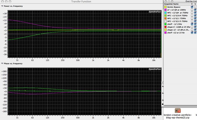
1. When I turn the Gain on a band clockwise, the level of the band is decreasing, and when i turn counter clockwise is increasing. (Same probleme on each band)

2.  I'v Got MF3 on each channel don't working. strange. (In fact when I Turn the knob full CCW I'v got a boost of all the spectrum about 0,5db and CW a -0,5db on all the spectrum.)

I need your help.

Thanks  8)

Please help !  :'(


Hello gandhalf,

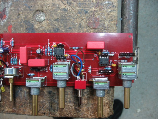
seems that all of your gainpots are reversed meaning you have the in and out of each pot swapped (the both outer pins).
This can only be achieved if you have mounted them off board (swapped the outer wires-easy fix!) or mounted them on the wrong side of the pcb!
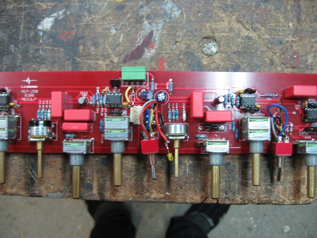
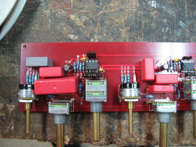
It would be helpfull if you can show us a picture of your pot-mounting.
For your MF3-issue (do you mean the third band from the left?) I can not help at the moment,but this is a differnt thing-maybe we can see more when we have the pics.

Hope to have helped,

Udo.
 
Hello, I'm talking about the 4th from left.


here are the pics :

5223722290_dc7d0c33ac_z.jpg


5223125813_fab9c4fedd_z.jpg


5223722580_d80008c6ce_z.jpg


http://farm6.static.flickr.com/5288/5223126101_cc23d61c00_b.jpg

http://www.flickr.com/photos/26322174@N03/5223127255/in/photostream/
 
I think you swapped 2 wires from the filterboards to the summing boards (see schematic), otherwise i don't know what's wrong.
Concerning MF3, make sure you have the right caps in there, could be that it's boosting and cutting at 100khz instead of 1khz.  8)
 
Hi again,

after having seen your pics (always very helpfull!!!)  I think dagoose is right-must be the connections from eq to op/summing-even more easy to fix ;)

Good luck to you-and do not forget to check the cap values on MF3 (super good tip of dagoose again).

Udo.
 
thanks for your help.


Here are the pictures of the condo in the High/medium frequecy band. (the 4th from left.)

5223682785_edebf30071_b.jpg


5224280780_9dbb9b941c_b.jpg


5224281160_8de3cf6f3c_b.jpg


5223683931_eb983d7eae_b.jpg


Hi gandhalf,

CHMF3 seems to be wrong.
I do not know the (black) caps you used but if it is the code written on it then 150 means 15pF.
Not 100 percent sure but looking at the schemo it will be wrong then(says 0.15).
If this is it then also check CHMF4 because code 100 will mean 10pF (schemo says 100).
The rest of the caps look o.k. on the first sight.
Maybe dagoose or Igor can clear it up?

And did you have success with swapping wires?

Udo.
 
thanks a lot for your advises. I'll try with a new cap. and for the polarity problem I think that my measuring software switched the reference curve with the measured one. so polarity switched.

 
gandhalf3 said:
thanks a lot for your advises. I'll try with a new cap. and for the polarity problem I think that my measuring software switched the reference curve with the measured one. so polarity switched.

Good to hear that you have the first problem solved,but it seems to me therefore that you have only measured your eq with some measuring software and did not listen to it?
If so may I give you an advice-TRUST YOUR EARS (you would have heard that....) ;D

Now you are on track I think....thanks to harpo for clearing the cap issue-did not know these types so it was very helpfull for me either as I  am about to build some of them in the near future (...if my work does not kill me before that ;).

Cheers,

Udo.
 
well done boys. I'v changed the presumed 0,15U who was in fact 150p.  Now all bands work great, sound good. but i found the noise floor a little bit high (i'v put the OPA604 )

here are some curve. If someone could say if they are right. i' have some doubt about the LF band in shelf mode.

5229895716_8834cd1c65_z.jpg


higher resolution http://farm6.static.flickr.com/5241/5229895716_8834cd1c65_b.jpg

5229895462_9eb377ae5f_z.jpg


higher resolution http://farm6.static.flickr.com/5043/5229895462_9eb377ae5f_b.jpg

5229302867_809f7a690c_z.jpg


higher resolution http://farm6.static.flickr.com/5209/5229302867_809f7a690c_b.jpg


Hi Igor/group,
I am wondering if it is possible/smart to vary the resistors next to the gain potentiometers to compensate for the 20% tolerance of these pots. Basically, what I am trying to achieve is that at its center-detent position the pot really doesn't have any boost or gain. However, measuring my pots it turns out most of them are pretty far off value, for example 52k from left to right leg, and 24k from left to tap (at center detent) and 28k from tap to right. For this pot, shouldn't I use a higher (than 4k75) resistor for RFxC and a lower one for RFxB? In this example, I would chose 5k75 for RFxC and 1k75 for RFxB.

The ideal case sum of resistors is: 4k75+50k+4k75 = 59k5

My real world sum of resistors is: 5k75+52k+1k75 = 59k5, (which it wouldn't be if I had stuck to the spec resistors)

Also the resistance from the CUT and BOOST buss to the potentiometer tap is more evened out, at center detent position.

Is this a good thing to do?
Thanks
Briomusic

ETA: I can't get hold of 1n5400 diodes is there another diode i can use? what is the disadvantage using normal 1n400x types? cheers
 
Brio: gain potentiometers already have CENTERTAP grounded,
and it doesn't matter so much 45K or 55K total resistance, and 0db will be exactly at center.
The DB/versus rotation angle may be bit different, but hey,
you want an action of precision 21-pos switch from potentiometer, which
in any case will be weared a bit within 3-5 years and give even more tolerance.
 
Ah, that's what the 4th pin on those pots is for. How exactly does it work?

Anyway, I will build a switched-resistor sontec at some point in the future, just wanted to bash one out cheaply and quickly, mainly for tracking purposes. I guess instead I will just use similar pots for the left and right channels respectively, so rotation angles are roughly matched (even if not accurate to silk screening).

Thanks,
Brio
 
hi everyone....

  i need some help, sorry about my stupid questions if the they are....i ve done several proyects but im a bit lost in electronics.

  1. how do i have to solder the toroid ??? i have an 2 x 24 V 50VA

    ive read in the forum  :

RED 25v
ORA 0v
YEL 25v
I connected the black wire to ~1 on the pcb, the red and orange wires to ~AB and the yellow wire to ~2

  But my trafo has 2 black wires , 2 red wires and 2 blue.....so how do i have to solder them???? and please i cant find ~1 and ~2 on the board, where are  they????


  2.which caps do you recomend for 33 uF ????  panasonic??? philips ???  elna????

  3.if my trafo is 24V i have to solder 3K6 on rx + and rx - , is that right???

  4.ive soldered all the 7K5 resistors on the pcb, do you recomend to change for 4K7 on the LF part????

  5.i have the 0,15 cap empty, which one works best on there????

  6.that resistor on the pots pcb.....FB 0...is that a jumper???? waht do i have to put on there????

  7. Where can I find a wiring overlay of the `proyect????  im completely lost about the cables, and the IEC power socket....

    thanks so much for your help


analogica said:
   1. how do i have to solder the toroid ??? i have an 2 x 24 V 50VA
     ive read in the forum  :
RED 25v
ORA 0v
YEL 25v
I connected the black wire to ~1 on the pcb, the red and orange wires to ~AB and the yellow wire to ~2

  But my trafo has 2 black wires , 2 red wires and 2 blue.....so how do i have to solder them???? and please i cant find ~1 and ~2 on the board, where are  they????
Colour coding of transformers is NOT standarized. Without giving a hint on manufacturer and type of YOUR transformer, no one can seriously help you. Updating your profile with your location might further indicate, this info is needed for 115V, 230V, 240V or whatever AC mains from your wall outlet.

  3.if my trafo is 24V i have to solder 3K6 on rx + and rx - , is that right???
Maybe, maybe NOT. http://www.groupdiy.com/index.php?topic=27972.msg497711#msg497711

  5.i have the 0,15 cap empty, which one works best on there????
A 150nF cap with the correct pin spacing.
 
analogica said:
2.which caps do you recomend for 33 uF ????   panasonic??? philips ???  elna???? 
Panasonic FM works well.

4.ive soldered all the 7K5 resistors on the pcb, do you recomend to change for 4K7 on the LF part????
4K7 gives +/-12dB gain, depends if that's what you want for the LF band (or any other band). Up to you.   

6.that resistor on the pots pcb.....FB 0...is that a jumper????
Yes. Or a ferrite bead.
 
thanks indeed guys!!!!

  im looking for my trafo on internet but i cant find the info...

    EYRA 230 V 50/60 Hz  sek: 2 x 24 50VA  as i said , 6 wires , two blacks , 2 blue, 2 reds  has somebody the same???

    which value do i need then for rx resistors???? variable trim is the better choice or 3K6 just works for it????


    thanks again


Latest posts

Back
Top