sontec 1 RU build thread

GroupDIY Audio Forum

Help Support GroupDIY Audio Forum:

This site may earn a commission from merchant affiliate links, including eBay, Amazon, and others.
analogica said:
  im looking for my trafo on internet but i cant find the info...

   EYRA 230 V 50/60 Hz  sek: 2 x 24 50VA  as i said , 6 wires , two blacks , 2 blue, 2 reds   has somebody the same???

   which value do i need then for rx resistors???? variable trim is the better choice or 3K6 just works for it????
Answer is depending on what supply voltage your opamps can take.
Your chips might only stand +/-18V or +/-22V, so you can rescale the needed value from 3K6 for +/-24V to the allowed supply voltage for your opamps.
Your 'EYRA' might be a typo and manufacturer iswas 'ERA' for real.
For usual, all needed info is printed on a label at your whatever toroid-/block-/EI-core- ..transformer.
 
I'd like to add 6dB input & output trim. Is this as simple as varying the feedback resistors in the input & output amplifiers from 20k down to 10k given that G = Rf/Rin. I figure changing both feedback resistors at once in the differential input amp would preserve the common mode rejection and give the correct gain reduction...For the inverting output only one resistor would need to be variable.

This would save me messing around with bridged T or "unbalanced floating" attenuators etc.

Is there some snag to varying the gain via the feedback resistors?


    thanks guys....i really need you,more doubts:

  1.i read this :somewhere  :  BYPASS PCB:  1m cap = 1.8uF - 2.2uF is fine there....is that right??? can i use in the 100m caps on filter board????

  2.i cant find the eyra or era trafo on internet....can somebody help me with the wires????

      My OPs are the 604, so how do i solder it???  i have 2 red wires, 2 blue and 2 black, which one goes to 1 , to 2 or to grnd ????

  3.And about the wiring inlay....im trying to understand the pcbs and the arrows but im lost,


  Sorry to be a pita guys but this is mi first proyect without a manual....

    thanks indeed

 
analogica said:
1.i read this :somewhere  :  BYPASS PCB:  1m cap = 1.8uF - 2.2uF is fine there....is that right??? can i use in the 100m caps on filter board?
Please include a reference number (such as C12, R123, IC-2, ..) for a part in question, so we're talking about the same object. Your question is probably related to the 1m=1uF cap (C in) on Input/Summing PCB. If so, 1.8uF - 2.2uF is fine as well, if you can make this larger sized cap fit on PCB.
I have no idea what you are asking about the 100uF caps on filter board.

2.i cant find the eyra or era trafo on internet....can somebody help me with the wires????
Why don't you read the sticker applied to this whatever type transformer and post this. A close up picture from this label might help as well. If this label says 'ERA' or 'era Elektrotechnik', this german company now is owned by 'Pulse GmbH'.

My OPs are the 604, so how do i solder it???  i have 2 red wires, 2 blue and 2 black, which one goes to 1 , to 2 or to grnd ????
Only two (or 4 for stereo) of your opamps are the OPA604. The remaining ones are NOT.
If all of the remaining dual opamps are OPA2604, +/-24V supply voltage would fit, so Rx is 3k6.
If at least one of the remaining dual opamps is an AD706, NE5532 or another one with lower max.supply rating, +/-24V supply voltage would/might blow this opamp.
 
I would like to add a post-gain control to my sontec, to compensate for level differences caused by eq-ing. Can i replace the 20k resistor in the feedback path of the output opamp with a 10k resistor and a 20k variable resistor in series? Would I need a lin or log pot?
original:
gain_ctrl_before.gif

pot added:
gain_ctrl_after.gif

 
Hi briomusic, this is similar to what I asked 4 posts ago.

Unless I'm mistaken, you'd need a log pot and would have between -6dB and +3.5dB of gain if you did things this way. I don't know what issues (if any) changing the feedback resistance might cause....

Rf     Rin   Rf/Rin dB
10.00 20.00 0.50 -6.0
10.62 20.00 0.53 -5.5
11.25 20.00 0.56 -5.0
11.91 20.00 0.60 -4.5
12.62 20.00 0.63 -4.0
13.36 20.00 0.67 -3.5
14.16 20.00 0.71 -3.0
14.99 20.00 0.75 -2.5
15.88 20.00 0.79 -2.0
16.83 20.00 0.84 -1.5
17.82 20.00 0.89 -1.0
18.88 20.00 0.94 -0.5
20.00 20.00 1.00 0.0
21.18 20.00 1.06 0.5
22.45 20.00 1.12 1.0
23.78 20.00 1.19 1.5
25.17 20.00 1.26 2.0
26.68 20.00 1.33 2.5
28.25 20.00 1.41 3.0
30.00 20.00 1.50 3.5
 
Hi MrShhh,
yes i noticed your similar question, and was trying to bump the thread (with additional pictures to get attention)  ;D
can i ask you, why are you keen on variable input gain as well? this seems to be asking for trouble in terms of CMRR...? I am mostly worried about overloading the converter input post eq, if there is a lot of boosting going on.
cheers
Briomusic.

p.s. I like your formulas/tables and that would be exactly the gain range i am after! I think I am just going to give it a try the next time the case is open...
 
sorry about the last post..theres a problem on my replys

Danke schön Harpo!

  the reference of the 100m caps in think they are C1 - C22  or  C2 - C51, i have the old schematics...but they are the couple next to the ferrite bead, i soldered 220 uF, is that right on there???
 
the name of the trafo is EYRA, so i cant find the info, im still searching...i guess 2 red are the hots, 2 blue are the cold, and 2 black the ground...but which goes to ~1  ~2  or  ~AB...

and yes my ops are 2604 ap...so 24V should work

  thanks
 
briomusic said:
Hi MrShhh,
can i ask you, why are you keen on variable input gain as well? this seems to be asking for trouble in terms of CMRR...?
It's just an idea at the moment to add flexibility, not as useful as output trim but if it's simple enough...I think it's possible to preserve the CMR of the input but you have to change resistors R3 & R4 at the same time to match each other. It could be done with a stepped attenuator to get a good match at all settings. I'm not 100% sure if this is a good thing to mess around with, or if my reasoning is correct!

On a bit of a tangent, according to P9 of the IC Op-Amp Cookbook:

Common mode gain of a diff amp = 4d[Rf/(Rin+Rf)]
where d is the fractional unbalance of the resistors (1.0% = 0.01).

So if we have a 1% resistor mismatch in the unity gain diff input amp then:

CM gain = 4*0.01*[20k/(20k+20k)] = 0.02

This seems really high?? Is it wise then to use 0.1% matched resistors or better? Practically speaking, it probably doesn't matter, I'm just interested in the theory...

250InputAmp.jpg
 
analogica said:
the reference of the 100m caps in think they are C1 - C22  or  C2 - C51, i have the old schematics...but they are the couple next to the ferrite bead, i soldered 220 uF, is that right on there???
These will work if they are rated for at least 24V. Comon value would be 220uF/35V. Watch out orientation of these polarized parts.
   
the name of the trafo is EYRA, so i cant find the info, im still searching...i guess 2 red are the hots, 2 blue are the cold, and 2 black the ground...but which goes to ~1  ~2  or  ~AB...
Still you give no further information or pics of your transformer, but your guess will be wrong. This is a transformer, not a battery. 6 leads comming in/out and stating, its a dual secondary, would be one wire pair for primary winding, further connecting to mains switch - fuse - IEC-connector - 230VAC wall outlet, the remaining two wire pairs are your 2x separate windings 24VAC each. This isn't a center tapped transformer, but it can be wired to behave as such.

Get a multimeter, switched for measuring ohms and sort out the 3 pairs (or read the sticker applied to your transformer. If there is the manufacturers name EYRA printed on, there will be other/all information as well as symbols/signs/dots ::)). Your measuring result might come up with the pairing black/black- and red/red-, blue/blue- or red/blue, red/blue or another permutation. Looking close to the wire insulation, you might notice a thin white or black stripe at one of the black, red and blue wires, indicating the cold or out-of-phase wire end of this winding connection. 

For your 230:24+24 stepdown transformer, the primary winding wires (wild guessing maybe the black/black- wire pair) most often come with a smaller diameter (more turns, less current) than the secondary winding wires. If all wire diameters are the same, you want to be absolutely sure which pair connects to AC mains side before picking a wrong pair and have the transformer connected backwards (giving a frightening 2300VAC secondary instead). A VariAC or a small low voltage transformer (doorbell transformer,...) in front could help to sort this out with less lethal voltages.

For examples sake, assuming the secondary pairs as red/red- and blue/blue-, you want both of your 24VAC secondary windings connected in series, giving a single 48VAC secondary winding with this series connection being the center tap. This now combined single secondary winding has a hot/in-phase end (red) and a cold/out-of-phase end (blue-), each further connecting to either '~1' or '~2'. The transformers center tap junction (red- linked to blue) is further connecting to '~AB'.
 
Hi friends, im almost there....

  I have a few questions about the wiring...

  1. how do i have to solder the XLR boards???  what i see on the pictures is PS to filter board, and PS 2 to
      power board, is that right???    so i just have to follow the numbers from 1 to 4, right???

      I cant see it so clear,

  2.i have to solder XLR board ground to GRD on the power board, and add the the input ground on the plug, right???

  3. how do i have to solder the toroid to a ON/OFF switch???, just the AB wires ???

  sorry if my questions are silly, im lost

    thanks again
 
1. how do i have to solder the XLR boards???  what i see on the pictures is PS to filter board, and PS 2 to
     power board, is that right???    so i just have to follow the numbers from 1 to 4, right???

     I cant see it so clear,

Just connect PSU board to PS, and go from PS2 to Filter board. For making sure the + to - follow the traces on the board.
2.i have to solder XLR board ground to GRD on the power board, and add the the input ground on the plug, right???

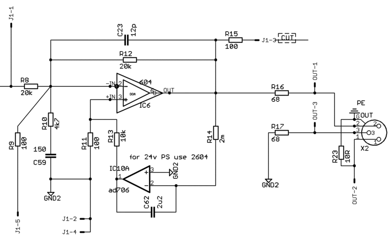
If you take a closer look under the summing board, you will see that there are two different plane grounds, one for the XLR's that has to be connected to your star ground, and the other that is connected to your PSU ground.
Do a star ground hooked to the chassis with a steardy knut and a screw, and it's better to take out the paint where you connect this star ground, powder coating can make a bad contact, and here you will connect the IEC Ground, the PSU ground, and the Audio (XLR) Gnd.

3. how do i have to solder the toroid to a ON/OFF switch???, just the AB wires

First make sure this and that you're using the toroid the right way:
http://www.diyfactory.com/data/transformer_connections.gif


Normally you would like to cut the Phase ( L in the file above) of the Main IEC. Some like to cut both neutral and Phase.
Meaning you have 3 points on the back of your IEC, one that must be the neutral, one that must be GND (Goes to Star Gnd), and the Phase that is connected to your fuse if you have a fuse inlet IEC Socket? Check wich is wich.
From the phase you go to your switch, and from there you connect the phase of your toroid.
The neutral of the toroid goes to Neutral of the IEC Socket.
This is for if your IEC socket has the fuse inside, if not then you have to connect the Phase from the IEC socket to the fuse socket (has two solder hears for that) and from the fuse socket to the switch etc...

All this means you cut the primary section not the secondarys of your transformer, you said AB, but that is the connections of the secondary "Center Tap" to the PSU board, be carefull.
You understand that when the primary is feeded, then you have power on secondary, so if you cut secondary, then that means main power always on and toroidal always feeded  :eek:...

IF you still feel lost, then look at some pictures here and there, you'll get the point.

ANd Last but not least, don't fit any of the IC's and no DOA's, until all voltages are checked at all MAJOR points.

I personnaly like to start by checking the PSU first, and there you can check if your switch wiring is ok for you in example and you wire to main boards after checking if the PSU outputs are correct and at the right points.

Hope this helps???

EDIT: Make sure the switch you use handles 250V and more than 1A, don't use tiny dc switches for that purpose, maybe that you knew, but better be safe than sorry...
 
Hi All

I just checked out the ALPHASTAT 50K gain pot on my sontec that I built and the pin above and slightly to the right of pin 3 which I thought was the center tap doesn't :

A) short to ground on the PCB

B) short to the wiper when at center detent position

however it does short to the outside of the pot.

Am I missing something here???  can someone else check with a multimeter to confirm this?

would be great if someone can shed some light on this.

thanks in advance
 
Are you talking about potentiometer case pin?
The PIN4 is center tap, it is locared at the left side of pot if you looking from front.
 
Hi Igor

Thanks for the reply.

I just checked it again and the reason it didn't show continuity was because there was 68 ohms difference between the two pins.  All good.

If I was going to use a non center tapped pot for a build of this circuit, would it work ok if the wiper was just switched to ground when you want it out of circuit?
 
this thing just saved my life rescueing a really badly recorded vocal (verse and chorus recorded in different studios etc).
can't wait to have a switched version to use confidently in stereo!  :)
 
hey fellows....i have problems again

  the unit is finished and working but the channels doesnt work the same way,

  1. the unit off has a small hum sound when I put the plug on the power socket, so it seems a ground problem, ...the screw to hold the toroid is the same where i place the main ground star....do you think it can be the problem¿???¿?....where can i check then???

2.in the first channel if i turn down a pot it affects to signal more than on the other....so the signal is more muddy and smaller(almost dissapear) than on the other channel
 
And if I amplify on the other channel the sound is brighter always...wheres the problem????

If turn ON the EQ on both channels with the pots on 0, the signal is the same...so is that a problem on the summing board???? i have no clue how or where to check this.

  hope you can help me...thanks guys


Latest posts

Back
Top