Okay, here's a basic troubleshooting run-through:
First print out the Schematic from
here, and refer to it as you go through the troubleshooting.
First checks:
When switched to Turbo mode and with SILENCE at both inputs, the turbo TL074 outputs for pins 1 and 7 should all have 0Volts DC and 0 volts AC on them. Pin 14 should have a fixed DC voltage on it which varies as you switch through the three available ratios. This should match the same exact thing happening at pins 1, 7 and 14 respectively on the main board TL074. On the turbo board, pin 8 should have a DC voltage on it which varies as you adjust the "threshold" control.
All good? -Moving on:
Now, leave the compressor switched to 2:1 ratio, with the threshold set to LEAST sensitive... i.e. compressing the least. -Apply a steady tone at a decent signal level (about 0dBm: -In fact anywhere between a 0.5 -to- 1 Volt is perfect) to BOTH inputs. Verify that the outputs of BOTH of the input 5534s on the main boards have a similar
AC voltage at pin 6.
Next, leave the meter switched to
AC, and measure the voltage at pin
7 of the main board TL074. -You should see that the signal voltage rises and falls as you vary the threshold control. -You see that? -Then make the same measurement at pin 7 of the Turbo board TL074, and you should see the same thing. -In fact you should see basically the SAME voltages for all settings of the threshold control.
All good? -Moving on:
Now meter the signal at pin 1 of the Main board TL074. -It should now have BOTH and
AC and a
DC component, and how much of each you will measure depends on your meter. -If you have an oscilloscope, you should be able to see a "multiple-camel-hump" sort of a waveform... once more, It will vary in amplitude (and at very low levels, slightly with shape, but don't worry about that...) with the threshold control. -Basicallty, for each setting of the threshold control, BOTH TL074s should have the same sort of shape waveform at pin 1, and whether your AC voltmeter meter is averaging, true RMS, or just making a guess at the waveform, -so long as the readings for each meter setting (AC and DC) are similar for each position that you set the threshold control to, then all is good.
All good? -Moving on:
Now meter the signal at pin 14 of the Main board TL074. -It should now have BOTH and
AC and a
DC component, and once again it shoudl agree with the same numbered pin on the Turbo board TL074. This time there will be a DC offset (this is the threshold).
(By way of explanation of the SSL circuit here: -the unit starts compressing as the voltage transitions through zero volts, and so the 'DC offset' with silence at the input is the 'threshold' which the rectified signal has to overcome in order to begin compression.)
The threshold control should-once again- have a significant effect once a decently-sized signal is present (and -of course- no effect whatsoever when the input is silent) thus determining how easily the signal 'forces' the voltage across the zero line.
If you get the same signal at pin 14 also, then the only thing before the output of the board reunites with the main board is the 1N4148 diode which goes to point 'C'.
That's all there is to troubleshooting the board in terms of diagnosing and locating the area where things may be going wrong... -Double-check the orientation of the diodes of course.
If you have access to a scope, the
shapes of the waveforms should look similar, as well as the amplitudes, and this makes troubleshooting a breeze of course... but nothing should be impossible even with just a modest multimeter.
Pete, let me know how it goes and what you find.
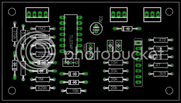
The Turbo is essentially the same as the sidechain section in the GSSL version from the 47k resistors on the left (where the signal splits) to point 'C' (where the signal reunites), and so you should be able to easily see what it should be doing, and you should have a 'working model' on the main board, in order to make comparison readings and measurements.
Report back with your findings. -nothing shall defeat us! :wink:
Keith


") but you never know..
but you never know..