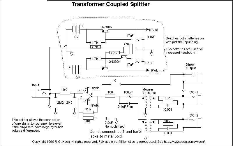
I'd like to build one of these but I generally fall flat on my face when it comes to translating a schematic into a PCB layout.
This time, I've tried to let the computer help me by putting the schematic into ExcpressSCH and doing a board design in ExpressPCB.
I've had a bit of trouble just getting all the traces to route without wanting to crisscross, but I think I've finally got all the connections in place.
If anyone could take a look at this and let me know if it's all connected properly I'd really appreciate it.
I'm sure there are better ways to do it, too, so if you have suggestions on what to do differently please feel free to post them.
Here is the original GEOFEX schematic:

My version of the schematic:
http://www.ryanadam.com/splitter/SplitterSchem.jpg
My PCB:
http://www.ryanadam.com/splitter/SplitterPCB.jpg
I've also placed the schematic and pcb files for the ExpressPCB programs in the folder with my images.
ExpressSCH file:
http://www.ryanadam.com/splitter/Transformer Coupled Splitter.sch
ExpressPCB file:
http://www.ryanadam.com/splitter/Splitter.pcb
This time, I've tried to let the computer help me by putting the schematic into ExcpressSCH and doing a board design in ExpressPCB.
I've had a bit of trouble just getting all the traces to route without wanting to crisscross, but I think I've finally got all the connections in place.
If anyone could take a look at this and let me know if it's all connected properly I'd really appreciate it.
I'm sure there are better ways to do it, too, so if you have suggestions on what to do differently please feel free to post them.
Here is the original GEOFEX schematic:

My version of the schematic:
http://www.ryanadam.com/splitter/SplitterSchem.jpg
My PCB:
http://www.ryanadam.com/splitter/SplitterPCB.jpg
I've also placed the schematic and pcb files for the ExpressPCB programs in the folder with my images.
ExpressSCH file:
http://www.ryanadam.com/splitter/Transformer Coupled Splitter.sch
ExpressPCB file:
http://www.ryanadam.com/splitter/Splitter.pcb


