the Poor Man 660 support thread

GroupDIY Audio Forum

Help Support GroupDIY Audio Forum:

This site may earn a commission from merchant affiliate links, including eBay, Amazon, and others.
WIRING GUIDE

working on this at the moment, feel free to report possible mistakes.
it is not completed right now, but the more complicated connections are in.

http://groupdiy.silentarts.net/pm660/PoorMan-WiringGuide.pdf
 
It would be great if that would work.
Than we could use these switches.
http://www.uraltone.com/kauppa/product_info.php?products_id=1077


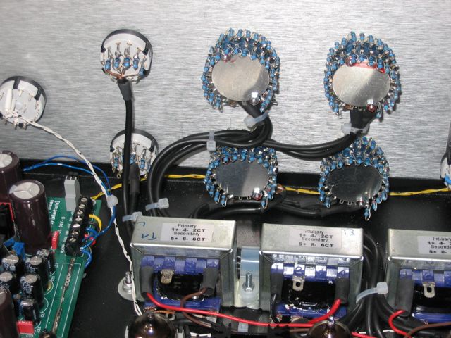
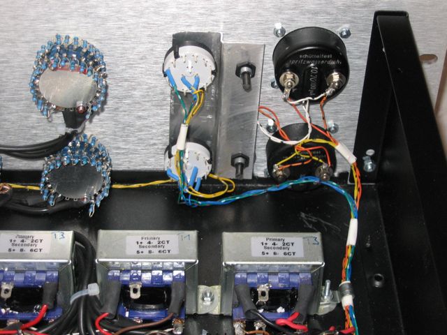
These are exactly the same switches I use for my prototype. Haven´t finished soldering the resistors yet, but the quality of these switches is great.
regards
Bernd

regarding these switches, can they be stoped at other positions? e.g 21 steps ?
 
Hi Volkar or whoever may assist.

I am wondering if it as at all possible to provide a wiring diagram for this project simmilar to that provided by guys like Joe at JLM Audio here:
http://www.jlmaudio.com/JLM%20Dual%2099v%20wiring%20overlay.pdf

I realise that many will do different variations but for those like me who will stick with the original plan and common transformers and switches etc.. it would save novices like me from a potential catastrophie.

Pleeeeeze :razz:
 
I am having trouble getting my head around these stepped attenuators. I have the same ones that Bernd is using. Maybe someone can post a simple diagram for hookup? I have been looking to no avail......

Thanks everybody,
David
 
[quote author="bernbrue"]Hi there,
some people asked for a picture of how to set up a rotary switch for the PM670. I used the Uraltone switches 2 decks 24 positions. In order to limit to 21 positions, you have to open the screws of the switches and make your own stopper with a piece of plastic (attention: hold together the blue rings with the contacts, otherwise the switch will fall apart) Use Volkers Excel calculator to find the resistor values for a 15k log pot. Here is a picture of how I soldered the resistors (not nice but not too bad for the first try)


Uraltone_switches_004.jpg


regards
Bernd[/quote]
 
Thanks!!

i saw that info a while back but overlooked....didnt realize they are the same switches.....everything clear now :thumb:
 
[quote author="rrs"]I am wondering if it as at all possible to provide a wiring diagram for this project simmilar to that provided by guys like Joe at JLM Audio here:
http://www.jlmaudio.com/JLM%20Dual%2099v%20wiring%20overlay.pdf[/quote]
:?: :?: :?:
http://www.groupdiy.com/index.php?topic=28274&postdays=0&postorder=asc&start=444

still a work in progress, but what does it looks like :green:
 
sorry for my electronics ignorance. i have tried to research befor asking but why is a 2 deck attenuator needed for each single channel. perhaps i dont understand the difference between the attenuator in the compressor as opposed to an input or volume attenuator on a preamp or amplifier?
can someone explain?
does anyone have a source for the uraltone switches in north america?
thanks
 
[quote author="[silent:arts]"][quote author="rrs"]I am wondering if it as at all possible to provide a wiring diagram for this project simmilar to that provided by guys like Joe at JLM Audio here:
http://www.jlmaudio.com/JLM%20Dual%2099v%20wiring%20overlay.pdf[/quote]
:?: :?: :?:
http://www.groupdiy.com/index.php?topic=28274&postdays=0&postorder=asc&start=444

still a work in progress, but what does it looks like :green:[/quote]

How did I miss that ?
It was on the same page. :shock:

Looking Great and easy to follow so far.

Big Thanks :thumb:

[edit] actualy thats odd, I posted that before you put it up. The posting times seem out of order :?:
 
Hi,
here´s a chart with an English translation of the PM670 power transformers wire colors from the European groupbuy:

normal_groupbuy_powertx_002.jpg


  • R2-0134-002 Rondo 134VA
    Prim: 2x115V yellow-white / yellow-white
    Sek.1: 250V/0,2A black/black
    Sek.2: 9V/6,0A grey/grey
    Sek.3: 2x15V/2x1,00A red-green/white-blue
    tx shielding: green yellow (connect it to ground)

Volker, would you please set a link to this post on 1st page?
regards
Bernd
 
Hi


can ant one tell me what this means 0,6W ? .Does it mean 1/2 watt ,if not can anyone point me in the right direction where i can buy single resistors for the crippling man.


regards

skal1
 
skal1

1/2 watt means 0.5W and 0.6W means a tad over.

I used the Axial 0.5W/0.75 1% metal film from RS Components.
Tight bend on the leads and they just fit on the PCB
 
Hi Bernd,

fantastic build! Any chance of another beautiful piano sample?, I was just listening to your earlier sample this morning.

BTW I hadn't forgotten your request about the meter scale, I found my scanner and my old laptop with the drivers. I am taking apart the meter now. Only thing is that I think yours are quite different to mine but you should be able to adapt it.

Will be in touch.

Cheers,
Ruairi
 

Latest posts

Back
Top