You are using an out of date browser. It may not display this or other websites correctly.
You should upgrade or use an alternative browser.
You should upgrade or use an alternative browser.
the Poor Man 660 support thread
- Thread starter [silent:arts]
- Start date


Help Support GroupDIY Audio Forum:
This site may earn a commission from merchant affiliate
links, including eBay, Amazon, and others.
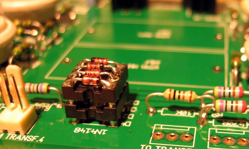
Yes, but at high current points. This Project has no such a points except some PSU and heater PSU. Now you will ask why I soldered the resistors this way ??? Well, I like to have option to de-solder things and possibly mod some stages. Instead of hundred times de-solder-solder things on PCB you can just cut the legs and you will have perfect solder placesIs raising the resistors like this recommended?? For heat reasons?
")
Hmm, I was thinking about that (and about hundred other things PM660 related) a lot. I still didn't connected the "thing" because of that.Benny why did you mount the transformers in line and close together? Whats your crosstalk between transformers?
Placing 8 transformers plus one 150W power transformer in one case can be a real mess. I know that "it will work" just with placing anyhow, but how, that's the question. What about surrounding the each transformer with steel shield... Well, that will interact with TX core somehow, but crosstalk will be better ???
Siegfried Meier
Well-known member
Another good reason to have gotten this...
http://www.groupdiy.com/index.php?topic=28299&postdays=0&postorder=asc&start=30
Ok, so if I put the resistors flat there should be no problem then, right? I don't really plan on modding this thing at all, I just want it stock.
Still having problems finding this heater resistor - someone mentioned Mouser, but has anyone that has the above power transformer found anything that will work for them? I'd like to complete my Mouser order today and get these parts here ASAP.
Thanks!
Sig
Right ;DOk, so if I put the resistors flat there should be no problem then, right?
rrs
Well-known member
Benny said:Yeah, you can finetune how poor you are with those things...
Just kiddin'. I used those things as measuring points for the trimmers.
Didn't want to measure from under the pcbs while the unit is on.
I was thinking about this myself and I the first thing I thought when I saw your picture.
I am wondering if this can be measured from somewhere else (say the following component)?
mikeyB
Well-known member
Can I just use IRF840 in place of 820 - higher current - but is there any reason why it MUST be an 820? Want to get break price and use others for valve tester rig
[silent:arts]
Well-known member
yesmikeyB said:Can I just use IRF840 in place of 820
on the PSU PCB ?AW_music said:i have a question about C13, C14 and C23, C24...
may i use wima 0,1uf rated 63 volts?
yes
bassculture
Well-known member
hi
1/ thanks i got my pcb today ! reliable & fast shipping ! thank you !!
2/ is 4,7K 25turns trimmers ok for the 5K trimmers on the PSU ? any chance we have to turn them to 5K ?
will those can be also ok for the audio PCB as well (enought prescision ?).
1/2w is ok ?
3/ is that rectifier ok ? (Taiwan Semiconductor KBU 1006 Bridge Rectifier, In-Line. 10A, 560V(RMS) 5/5mm)
see there : http://www.banzaieffects.com/KBU1006-pr-24042.html#tabs
does it gets hot ?
4/ i'm building PM670 (1 PSU). what value of the 50W heater resistor do i have to pick up ?
i didn't order them by now, but i'll stick to the tubes you recommend.
thanks
thanks !
bassculture, please read this thread from 1st page. Almost everything is answered many times 8)
Siegfried Meier
Well-known member
Almost everything, yes, except for the heater resistor, which I'm still trying to find. It is so dependent on the power transformer and tubes you use. I didn't want to stick a varistor in there personally, and was hoping someone was using the big huge bad ass 670 Avel Lindberg toroid that Kid Squid was selling, as that's what I have. But there also hasn't been very many successes in this project yet, I count only 3 or 4 finished units that I've actually seen on here.
If we do go with a varistor first, then find the value and replace, does anyone have the correct part number for this on Mouser? There are like a million to choose from.
Thanks!
Sig
If we do go with a varistor first, then find the value and replace, does anyone have the correct part number for this on Mouser? There are like a million to choose from.
Thanks!
Sig
jdbakker
Well-known member
Siegfried Meier said:[...] varistor [...]
Nit: a varistor is a voltage dependent resistor, and probably not what you mean here. To find the proper resistance you could use a rheostat.
JDB.
[or get a dozen low-value power resistors and attach them in series/parallel until the proper voltage is reached. More resistors = easier heat dissipation, and tube heaters are forgiving enough to accept brief overvoltage blips]
Siegfried Meier
Well-known member
Doug, can you get me the actual part # of what you used?
Thanks!
Sig
Thanks!
Sig
If you want to save the money then go with fixed resistor as designer stated. If you want to be precise in the filament voltage then it's much better if you go with regulated slow turn on supply. Rheostat is expensive and you still depend on the mains voltage, so you are precise as your country or area voltage I decided to go with two LM338 for stereo unit . It saves the tubes life it's precise and it's cheaper than varistor.
Cheers ;D
I decided to go with two LM338 for stereo unit . It saves the tubes life it's precise and it's cheaper than varistor.Cheers ;D
Siegfried Meier
Well-known member
Can you show me a pic of how you did this Moby? And you're talking the LM338 voltage regulator? I'm quite confused now...aren't we talking about 2 different parts...?
[silent:arts]
Well-known member
regulated heaters are not a bad decision, but will need some good heatsinks.
Sig, look at the schematic of the D-AOC heater PSU as a start.
for a PM670 (stereo) you would need one for each channel.
Sig, look at the schematic of the D-AOC heater PSU as a start.
for a PM670 (stereo) you would need one for each channel.
I agree, but with resistor at 5 or 6A consumption you will have a heat anyway. Same thing, something have to burn the voltage from 12 to 6.3 V.... pure energy thing ;Dregulated heaters are not a bad decision, but will need some good heatsinks.
No we are talking about same thing but one is non regulated and the other one is regulated. Here is basic schematics I started from. Sorry I didn't included the values (hurry, hurryCan you show me a pic of how you did this Moby? And you're talking the LM338 voltage regulator? I'm quite confused now...aren't we talking about 2 different parts...?
) but they are in the LM338 datasheet anyway. Don't be confused with parallel parts Its because I wanted few footprints for part on my PCB... You just have to adjust the voltage with R4 (2k5 or 5k) to 6.3V. This approach is good because if you one day want to replace the Valves you can re-adjust the filament voltage easily. Yes, Two circuits like this for stereo unit.... 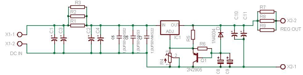
Gachet
Well-known member
That's interesting...
Even if you don't change the valves, this unregulated supply is problematic.
I'm using the poorman since one week next to my diy summing box and the heater voltage change from 6.4V at start to 6.2V 4 hours later.
There is some distortion (wich is not really annoying) at 6.4 and after 15 minutes distortion gone away heater voltage is 6.3V.
Another thing...
Did some people noticed that the 5687 are becoming very hot after 15 minutes.
The plastic socket are litteraly cooked by the heat of the valve.Is that normal?
I think I will change those sockets to ceramics ones.
No problem with 6bc8.
Besides those little things I want to thank analag and silent art for that project wich really improve my sound quality ;D ;D ;D ;D ;D ;D ;D
The musicians enjoyed the mix session with that vari mu.